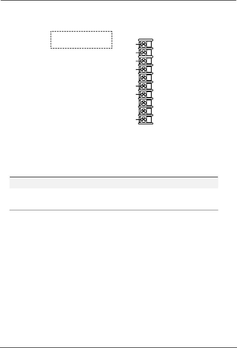
Inputs and Outputs Wiring
January 2009 UDA2182 Universal Dual Analyzer Product Manual 131
7.7 Dissolved Oxygen
Some cables have connectors on the leads.
Cut off the connectors, skin and tin the leads
and then wire to the screw terminals on the boards
Some cables have connectors on the leads.
Cut off the connectors, skin and tin the leads
and then wire to the screw terminals on the boards
Guard
RTH Low
RTH High
Earth Ground
Black*
Green
Yellow
Wire to chassis
ground screw
Signal
Name
Signal
Name
Wire
Color
Wire
Color
10
9
8
7
6
5
4
3
2
1
10
9
8
7
6
5
4
3
2
1
RTH Low
RTH High
Clear
Red
Orange
Cable shield (Blue)
to chassis ground screw
Cathode
Reference
Anode
* Older Dissolved Oxygen probes may have a
White/Black Guard wire instead of a Black Guard wire.
Some cables have connectors on the leads.
Cut off the connectors, skin and tin the leads
and then wire to the screw terminals on the boards
Some cables have connectors on the leads.
Cut off the connectors, skin and tin the leads
and then wire to the screw terminals on the boards
Some cables have connectors on the leads.
Cut off the connectors, skin and tin the leads
and then wire to the screw terminals on the boards
Some cables have connectors on the leads.
Cut off the connectors, skin and tin the leads
and then wire to the screw terminals on the boards
Guard
RTH Low
RTH High
Earth Ground
Black*
Green
Yellow
Wire to chassis
ground screw
Signal
Name
Signal
Name
Wire
Color
Wire
Color
10
9
8
7
6
5
4
3
2
1
10
9
8
7
6
5
4
3
2
1
RTH Low
RTH High
Clear
Red
Orange
Cable shield (Blue)
to chassis ground screw
Cathode
Reference
Anode
* Older Dissolved Oxygen probes may have a
White/Black Guard wire instead of a Black Guard wire.
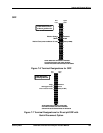
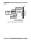
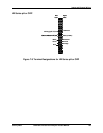
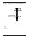
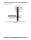
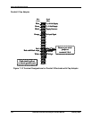
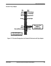
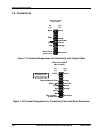
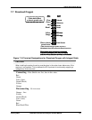
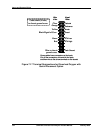
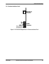
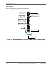
Figure 7-16 Terminal Designations for Dissolved Oxygen with Integral Cable
CAUTION
When installing the probe, the wiring must be done in the order shown below even if the
analyzer is not powered. This is because the DO Input card is continuously supplying a
voltage (bias) to the terminals.
Connecting – Blue Shield wire first, then in this order:
Red
Green
Coax (clear)
Guard (Black)
Yellow
Orange
Disconnecting – Go in reverse
Orange – first
Yellow
Guard (Black)
Coax (clear)
Green
Red
Blue Shield Wire


