


Configuration
58 UDA2182 Universal Dual Analyzer Product Manual January 2009
6.5 Analog and Digital Signal Sources
Overview
This section contains a list of signals that are available for connection as digital and
analog sources.
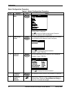
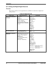
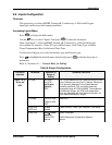
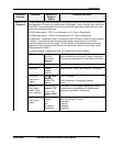
Table 6-2 Signal Sources
Signal Type Applies Source to: Selections
Analog Source Selections
(Table 6-3)
Alarms (PV)
Outputs
Math Blocks
Auxiliary - Function Generators
Monitor 1 through 4
Auxiliary - Switch (A,B)
Relays (Time Prop, Pulse Freq)
PID (RSP Source, Feedforward
Source)
None
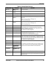
Input 1-2 PV
Input 1-2 Temp
Pharma Out 1-2
Math 1-4
Func Gen 1-2
Switch 1-2
Sum
Difference
Ratio
%Passage
%Rejection
Cation Value
PIDout 1-2
AnlgVar 1-4
PV Source Selections
PID 1 and 2 PV Source
Function Generator 1 and 2
None
Input 1 – 2 PV
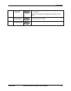
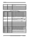
Digital Source Selections
(Table 6-4)
Logic (InA, InB)
Relays (Digital Out, Pulse out)
Auxiliary - Switch (Select B
Source)
Alarms Disable
PID (Remote setpoint select,
Manual select)
Auto Cycle – Start Source
None
Alarm1-4
Alm Grp 1-2
Monitor 1-4
Logic 1-4
Digital In 1-2
In 1-2 Fault
In 1-2 Hold
Out 1-3 Fault
Hold
Pharma 1-2 Fail
Pharma 1-2 Warn
PID 1 Alarm 1-2
PID 2 Alarm 1-2
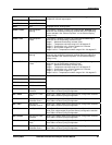
Auto Cycle 1 – Extract, Rinse, Cal PT1,
Cal PT2, Fail
Auto Cycle 2 – Extract, Rinse, Cal PT1,
Cal PT2, Fail
Input 1-2 Cal
Output 1-3 Cal
DgtlVar 1-4