


Configuration
54 UDA2182 Universal Dual Analyzer Product Manual January 2009
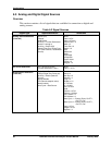
Proportional Output), Pulse Frequency (Pulse Frequency Type), Frequency Prop
(Frequency Proportional), or On/Off type and associated parameters.
Alarms Configuration ( Table 6-8) - configure Alarm 1 through 4 for Alarm’s
Source and associated parameters.
Monitors Configuration (Table 6-9) – configure Monitor 1 through 4 for
Monitor Type, Source and associated parameters.
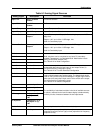
Math Configuration (Table 6-10) – configure Math 1, 2, 3, and 4 for Input
Source, Math Type, and associated parameters.
Logic Configuration ( Table 6-11) – configure Logic 1, 2, 3, and 4 for Input
Sources, Type, and associated parameters.
Auxiliary Configuration (Table 6-12) – configure Switch 1, Switch 2, Function
Generator 1 and Function Generator 2(for pre-control linearizing of inputs) for
Sources and associated parameters.
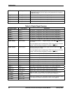
PID Control (Option) Configuration (Table 6-13) – configure:
PID 1 and PID 2 Configuration parameters,
Tune (Enable Accutune, Fuzzy Logic, Use Prop Band, Use RPM, configure
Tuning parameters) and
Alarms Parameters (Setpoint types and Values, alarm hysteresis)
Auto Cycling (Table 6-16) – enable Auto Cycle 1 and 2 and set rinse schedule and
associated parameters. Auto cycling provides automated timing, control and
functionality for the cleaning and calibration of input probes.
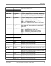
Variables (Analog Table 6-3 and Digital Table 6-4) selections can be read and
written remotely using Modbus function codes. You are setting up the initial values
for the variables when power is applied to the UDA (Refer to Table 6-18 for an
Example)
Communication Configuration (Table 6-19) – configure IR Front Panel,
Modbus, RS485 and Ethernet.
Maintenance Configuration (Table 6-20) – Configure:
System - read the Software version, configured Language, selected Mains
Frequency, and PID Control Selections, enter a Password, and reset the Unit.
Input 1 and Input 2 - configure Input types, Conductivity units’ type, wire
size, and wire length, and temperature Units.
Display – setup the Main Display Header; and Clear Event and Cal Histories.
Tag Names – configure tag name strings for input names on single channel
main display, Auto Cycle display header, Pharma display header, PID display
header. Alarm names to appear in status and event history.
Clock - set real time clock date; time; date format; and time format.
Tests - run Display and Keyboard tests, read Output levels, and read Relay
States.