


Configuration
January 2009 UDA2182 Universal Dual Analyzer Product Manual 61
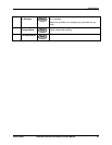
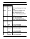
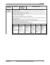
Out 1 Fault Output 1 Fault
Out 2 Fault Output 2 Fault
Out 3 Fault Output 3 Fault
Output open conditions. This allows an alarm to be triggered if the
respective 4-20 mA output opens.
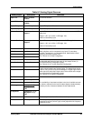
Hold Hold Engages Hold of Analog Inputs
Pharm 1 Warn Pharmacopoeia 1
Warning
The Pharma 1 Display ( Section 5.8) outputs digital Warning signal
whenever the measured conductivity exceeds the Percent Warning
Value selected in the “Pharma Op Panel” on the Pharma Display
(Stage 1only)
Pharm 1 Fail Pharmacopoeia 1
Failure
The Pharma 1 Display ( Section 5.8) outputs digital Failure signal
whenever one of the following conditions occur:
Stage 1 – Measured Conductivity exceeds 100%
Stage 1 – Temperature not within range of 0-100 degrees C
Stage 2 – Conductivity is 0.1 µS/cm or greater for 5 minutes
Stage 3 – pH not within range of 5 – 7pH
Stage 2 and 3 – Temperature not within range of 24 – 26 degrees C.
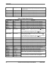
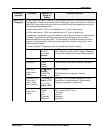
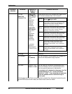
Pharm 2 Warn Pharmacopoeia 2
Warning
The Pharma 2 Display ( Section 5.8) outputs digital Warning signal
whenever the measured conductivity exceeds the Percent Warning
Value selected in the “Pharma Op Panel” on the Pharma Display
(Stage 1only)
Pharm 2 Fail Pharmacopoeia 2
Failure
The Pharma 2 Display ( Section 5.8) outputs digital Failure signal
whenever one of the following conditions occur:
Stage 1 – Measured Conductivity exceeds 100%
Stage 1 – Temperature not within range of 0-100 degrees C
Stage 2 – Conductivity is 0.1 µS/cm or greater for 5 minutes
Stage 3 – pH not within range of 5 – 7pH
Stage 2 and 3 – Temperature not within range of 24 – 26 degrees C.
PID 1 Alm 1 PID Control 1 Alarm 1
PID 1 Alm 2 PID Control 1 Alarm 2
PID 2 Alm 1 PID Control 2 Alarm 1
PID 2 Alm 2 PID Control 2 Alarm 2
Control Alarms – See Table 6-15 PID Alarms
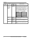
AC 1 Extract Auto Cycle 1 Probe
Extraction
Auto Cycle 1 digital output (Cycle Start Source) configuration selection
See Table 6-16 Auto Cycling Configuration.
AC 1 Rinse Auto Cycle 1 Probe
Rinse
Auto Cycle 1 digital output (Cycle Start Source) configuration selection
See Table 6-16 Auto Cycling Configuration.
AC1 Cal Auto Cycle 1
Calibration Point 1
Auto Cycle 1 digital output (Cycle Start Source) configuration selection
See Table 6-16 Auto Cycling Configuration.
AC 1 Cal 2 Auto Cycle 1
Calibration Point 2
Auto Cycle 1 digital output (Cycle Start Source) configuration selection
See Table 6-16 Auto Cycling Configuration.
AC 1 Fail Auto Cycle 1 Failure Auto Cycle 1 Failure is active whenever an Auto Cycle 1 failure occurs
Auto Cycle 1digital output (Cycle Start Source) configuration selection
See Table 6-16 Auto Cycling Configuration.
AC 2 Extract Auto Cycle 2 Probe
Extraction
Auto Cycle 2 digital output (Cycle Start Source) configuration selection
See Table 6-16 Auto Cycling Configuration.
AC 2 Rinse Auto Cycle 2 Probe
Rinse
Auto Cycle 2 digital output (Cycle Start Source) configuration selection
See Table 6-16 Auto Cycling Configuration.
AC 2 Cal Auto Cycle 2
Calibration Point 1
Auto Cycle 2 digital output (Cycle Start Source) configuration selection
See Table 6-16 Auto Cycling Configuration.