


Configuration
January 2009 UDA2182 Universal Dual Analyzer Product Manual 89
6.13 Auxiliary Configuration
Overview
The Auxiliary group has four selections (Switch 1 and Switch 2) and (Func Gen 1 and
Func Gen 2).
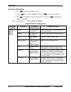
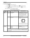
Switch
Switch selections have 2 input sources (A and B). A switch block is used to select
between two analog signals. The switch block can be used for many monitor and control
strategies. A Digital Signal Source (Table 6-4) when active will select the B input source
of the switch as the output.
The Switch Input sources can be any Analog Signal Source (Table 6-3).
There are two switch blocks provided for general use.
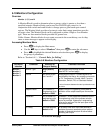
Func Gen (Function Generator)
Function Generators are used for pre-control linearizing of inputs (such as during pH
titration).
Function Generator selections have 2 input sources (Input 1 PV and Input 2 PV).
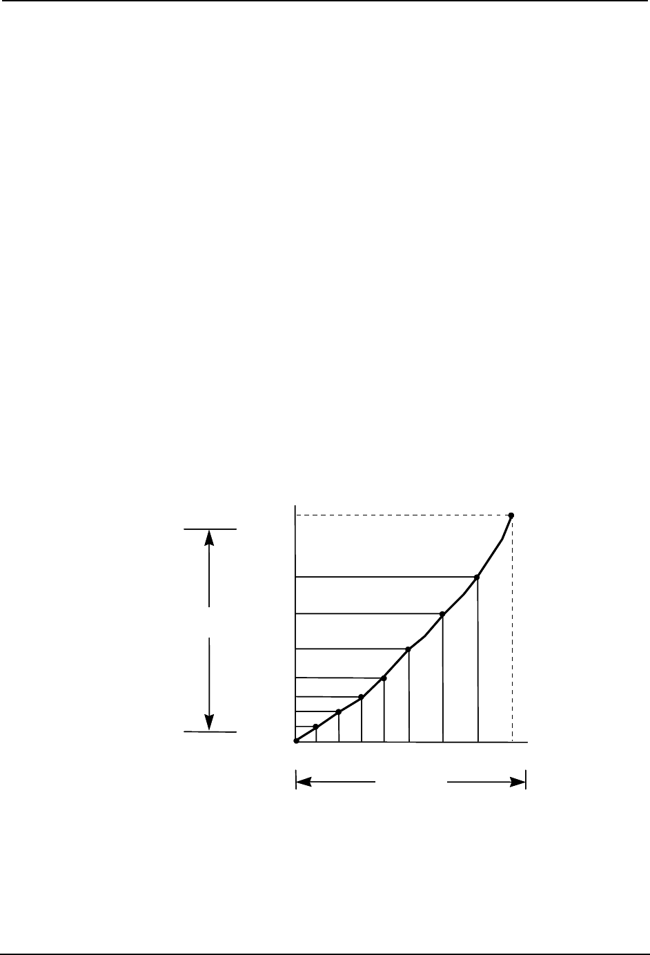
It generates an output characteristic curve based on up to 11 configurable “Breakpoints”
for both Input (X) and Output (Y) values.
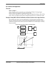
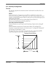
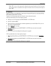
The figure below shows an example of using the Func Gen to characterize the PID
control loop output for control valve operation using 9 breakpoints.
OUT9
OUT8
OUT7
OUT6
OUT5
OUT4
OUT3
OUT2
OUT1
X1 X2 X3 X4 X5 X6 X7 X8
Compensating for control valve characteristic
100%
0%
0% 100%
FGEN
OUTPUT
PID OUTPUT
OUT9
OUT8
OUT7
OUT6
OUT5
OUT4
OUT3
OUT2
OUT1
X1 X2 X3 X4 X5 X6 X7 X8
Compensating for control valve characteristic
100%
0%
0% 100%
FGEN
OUTPUT
PID OUTPUT