Define a tag component Chapter 6
Rockwell Automation Publication 1756-RM084S-EN-P - March 2015 121
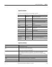
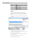
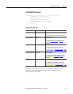
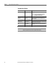
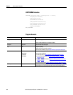
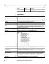
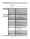
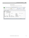
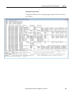
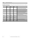
Attribute Description
AxisInfoSelect2 Specify a second axis attribute to transmit, and the actual position data, to the controller.
The options include:
• <none>
• Position Command
• Position Feedback
• Aux Position Feedback
• Position Error
• Position Int. Error
• Velocity Command
• Velocity Feedback
• Velocity Error
• Velocity Int. Error
• Accel. Command
• Accel. Feedback
• Servo Output Level
• Marker Distance
• Torque Command
• Torque Feedback
• Positive Dynamic Torque Limit
• Negative Dynamic Torque Limit
• Motor Capacity
• Drive Capacity
• Power Capacity
• Bus Regulator Capacity
• Motor Electrical Angle
• Torque Limit Source
• DC Bus Voltage
• Absolute Offset
• Analog Input 1 or Analog Input 2
• Absolute Offset
• Analog Input 1
• Analog Input 2
• Guard Status
• Guard Faults.
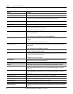
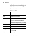
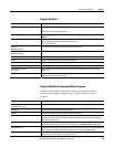
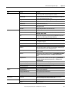
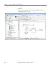
LDTType
Specify the LDT device type. Type PWM, Start/Stop Rising, or Start/Stop Falling.
LDTRecirculations Only use this field if you specified PWM for LDTType. Specify the number of recirculations that the transducer is configured for
so the 1756-HYD02 module knows how the LDT is configured.
LDTCalibrationConstant Specify the calibration constant (also called gradient on some LDTs). This number is engraved on each LDT by the
manufacturer. It specifies the characteristics of that individual transducer.
LDTCalibrationConstantUnits
Specify the units of the calibration constant. Type us/in or m/s.
LDTScaling Define the relationship between the unit of measurement of the transducer and the system. This is necessary for calculating
the conversion constant. The LDT length is used with the number of recirculations to calculate the minimum servo update
period.