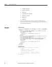
Define a tag component Chapter 6
Rockwell Automation Publication 1756-RM084S-EN-P - March 2015 131
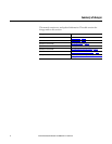
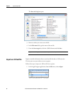
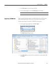
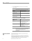
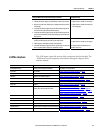
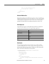
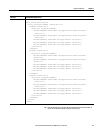
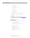
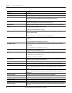
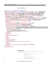
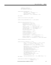
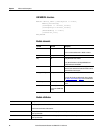
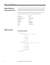
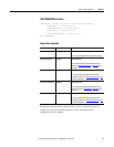
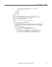
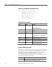
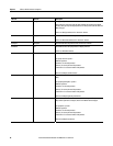
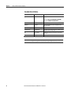
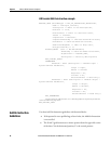
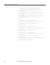
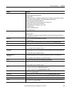
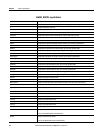
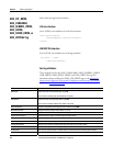
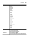
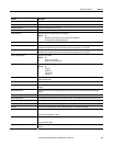
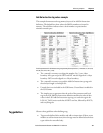
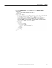
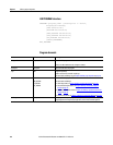
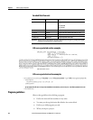
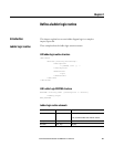
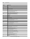
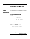
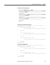
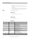
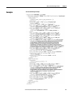
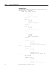
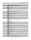
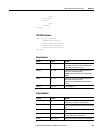
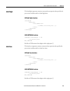
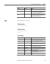
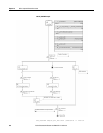
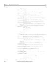
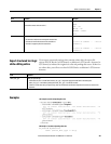
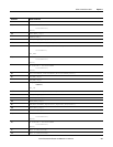
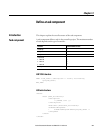
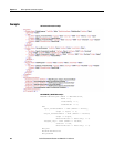
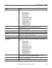
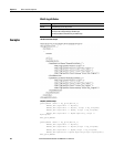
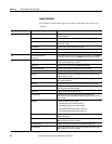
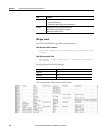
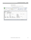
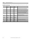
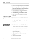
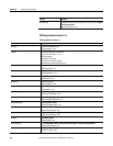
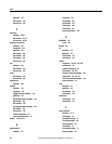
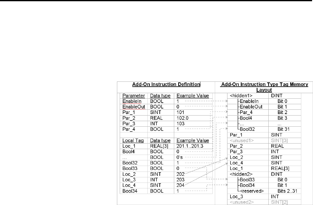
Add-On Instruction tag values example
This example demonstrates the tag memory layout of an Add-On Instruction
definition. The dashed lines show where the BOOL members are located in
memory. The solid lines indicate where a local member is repositioned to
minimize unused space.
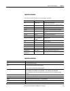
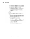
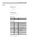
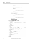
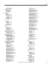
The L5K representation of an Add-On Instruction type tag containing the example values is: [-2147483643, 101, 102.0, 103,
202, 204, [201.1, 201.2, 201.3], 2, 203].
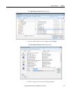
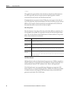
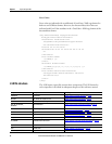
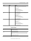
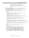
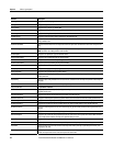
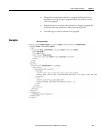
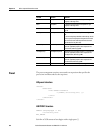
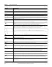
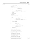
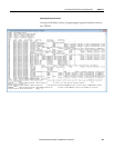
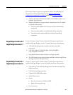
• The <unused1> memory area aligns the member, Par_2, on a 4-byte
boundary. All types except for SINT and INT must be aligned on a 4-byte
boundary. INTs must be aligned on a 2-byte boundary.
• The <unused2> memory area pads the Add-On Instruction type tag such
that the byte length is a multiple of 4.
• Unused data is not included in the L5K format. Unused data is included in
the L5X format.
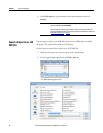
• The simplest way to guarantee that the order of the parameters and local
tags in the L5K Add-On Instruction definition matches the order of data
values in the L5K Add-On Instruction type tag is to order the tags in the
LOCAL_TAGS section such that all SINTs are first, followed by all INTs,
and everything else.
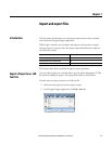
Observe these guidelines when defining a tag.
• Tags must be defined after modules and add-on instructions. If there are no
modules or add-on instructions, then the tags must be defined after the data
types within the controller body.
Tag guidelines