


88
CHAPTER 4 External Bus Interface
4.3 Area of Bus Interface
A total of six types of chip select areas are prepared as bus interfaces.
■ Area of Bus Interface
Each area position can be arbitrarily allocated in units of at least 64 KB in the 4 GB space by the area select
registers (ASR1 to 5) and area mask registers (AMR1 to 5).
Within the area specified by these registers, when the external bus access is performed to area 1 (CS1X),
the supported read/write signal (RD
, WR0, and WR1) will be active "L".
Note:
The area 0 is allocated to space other than the area specified by ASR1 to ASR5.
At a reset, the external area other than 00010000
H
to 0005FFFF
H
becomes area 0.
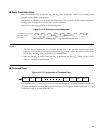
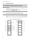
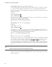
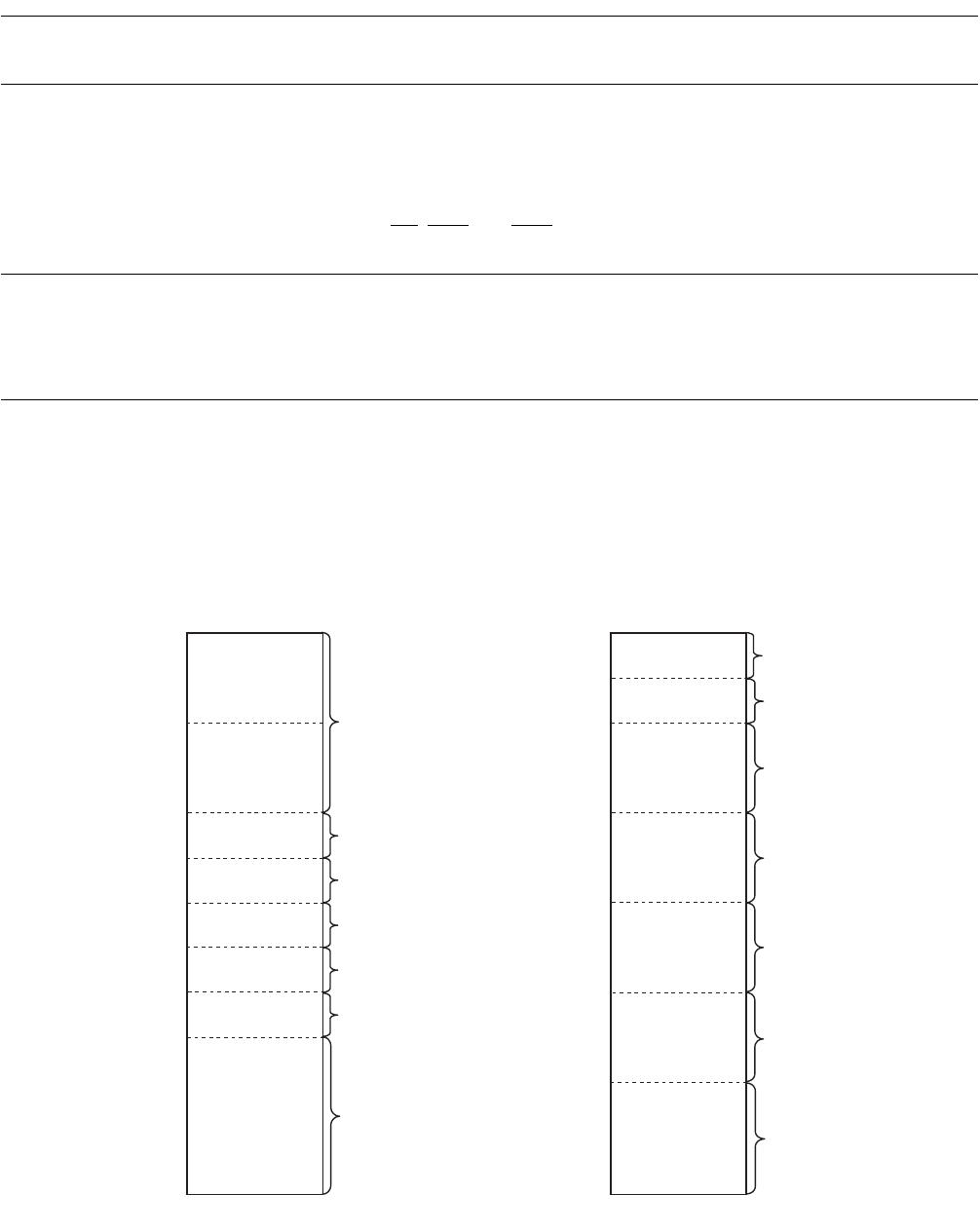
Figure 4.3-1 shows an example of area 1 to area 5 located in units of 64KB from 00100000
H
to
0014FFFF
H
. In the same way, examples in which area 1 is allocated per 512 KB from 00000000
H
to
0007FFFF
H
, and areas 2 to 5 are allocated per MB from 00100000
H
to 004FFFFF
H
are shown in Figure
4.3-1 .
Figure 4.3-1 Setting example of chip select area
00000000
H
00080000H
000FFFFFH
0010FFFFH
0011FFFFH
0012FFFFH
0013FFFFH
0014FFFFH
00000000H
00080000H
000FFFFFH
001FFFFFH
004FFFFFH
003FFFFFH
002FFFFFH
CS1X (512K)
CS0X (512K)
CS0X (1M byte)
CS2X (1M byte)
CS1X (64k byte)
CS3X (1M byte)
CS2X (64k byte)
CS3X (64k byte)
CS4X (1M byte)
CS4X (64k byte)
CS5X (64k byte)
CS5X (1M byte)
CS0X
CS0X
Region disposition example 1 Region disposition example 2