295
●
Auto writing or erasing operation
Bit 5 indicates that execution of the auto algorithm is exceeded the time prescribed within the flash memory
(number of internal pulse times). Bit 5 outputs "1" under this status. In other words, when this flag outputs
"1" while the auto algorithm is operating, it indicates that writing or deletion has failed.
Attempts to write bit 5 to non-blank areas without prior erasure may cause failure. In this case, defined data
cannot be read from bit7 (data polling), and bit6 (toggle bit) will continuously toggle. Under this status, if
the time limit is exceeded, "1" will be output to bit 5. Please note that this indicates that the flash memory
was not used correctly rather than any defect with the flash memory. If this event occurs, the reset
command should be executed.
[bit 3]:SETIMR (Sector erasing timer)
●
Sector erase operation
After the first sector deletion command sequence is executed, the waiting period for sector deletion is
indicated. Bit 3 outputs "0" during this period, and "1" if the sector erase wait period is exceeded. The data
polling and toggle bits are validated after executing the first sector deletion command sequence.
When "1" is set in this flag while the data polling or toggle bit function indicates that the erase algorithm is
being executed, an internally controlled erase operation has started. Writing of continuous command is
ignored until the data polling or toggle bit indicates the erase termination. (Input of deletion suspension
code only is accepted.)
If this flag is "0", the flash memory accepts the additional sector deletion code to be written. For
confirmation, using software to check this flag status prior to writing the sector erase code is recommended.
If "1" is shown at the 2nd status check, the additional sector deletion code may not have been accepted.
When reading is carried out while sector deletion is suspended. The flash memory outputs "1" if the address
indicated by the address signal belongs to the sector during deletion. If it does not belong to the sector
during deletion, the read value "bit 3" of the address indicated by the address signal is output.
[bit 2]:TOGGL2 (toggle bit 2)
●
Sector erase operation
This toggle bit is used to detect whether the flash memory is in auto deletion or suspension of deletion
status in addition to the toggle bit of bit 6. Bit 2 operates the toggle when continuously reading from the
sectors that have been deleted during auto deletion. If the flash memory is under deletion suspension
reading mode, bit 2 operates the toggle by continuously reading from the sector in which deletion is
suspended.
If the flash memory is under deletion suspension reading mode, "1" is read by bit 2 by continuously reading
from the sector in which deletion is not suspended. In contrast to bit 2, bit 6 toggles only during normal
writing, erasing, or erase suspension writing.
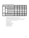
For example, bits 2 and 6 are used together to detect the erase suspension reading mode. (Bit 2 toggles,
whereas bit 6 does not.)
Bit 2 is also used to detect the deleted sectors. When the flash memory is being deleted, bit 2 operates the
toggle if reading from the deleted sector.


