71
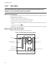
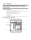
■ Transition to Stop Status
●
Transition to the stop state using an instruction
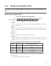
Write "1" to bit 7 of the STCR register to enter stop status.
After a stop request is issued, the status is changed such that the CPU does not use the internal bus, and
then the clocks are stopped in the following order.
CPU clock →internal bus clock → internal peripheral clock
The oscillation circuit stops when the internal peripheral clock stops.
Notes:
The following routine must be used to change the status to stop using a command.
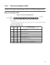
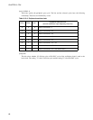
• Before writing to the STCR, set the same value to the CCK1, 0 and PCK1, 0 bit lots of the GCR, and the
gear ratios between the CPU system clock and peripheral system clock should be the same.
• Do not provide the stop state when the CHC bit of GCR is "0". To enter stop status, "1" must be set to
the CHC bit of the GCR, and 1/2 division system clock must be selected.
• At least five consecutive NOP instructions must be provided immediately after writing to the STCR.
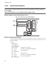
[Setting]
DI:8 #00000001b,R1 ; CPU=Peripheral gear ratio, CHC=1
LDI:32 #GCR,R2
STB R1,@R2
LDI:8 #10010000b,R1 ; STOP=1
LDI:32 #STCR,R2
STB R1,@R2
NOP ;
NOP ;
NOP ;
NOP ;
NOP ;
■ Return by Stop Status
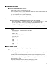
Returning from stop status can be performed by generating an interrupt or reset.
●
Return by interrupt
If the interrupt-enabled bit attached to the peripheral function is valid, returns from the stop status by
generating a peripheral interrupt.
Returning from the stop status to the normal operation status is carried out in the following procedure.
Generates interrupt -> Restarts oscillation circuit operation -> Waits for oscillation stabilization -> After
stabilization, restarts supply of internal peripheral clock -> Restarts supply of internal bus clock -> Restarts
supply of internal CPU clock
The program execution after oscillation stabilization waiting time is as follows.
• When the level of the interrupt is enabled by the I flag of CPU ILM


