


74
CHAPTER 3 CPU
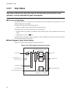
■ Transition to Sleep Status
To enter sleep status, write "0" to bit 7 of the STCR register and "1" to bit 6.
Issues the sleep request, and then stops clocks in the following order once the status of the CPU is changed
so that the internal bus is not used.
CPU clock → Internal bus clock
Notes:
The following routine must be used to change to sleep status.
• Before writing the STCR, set the same value to the CCK1, 0 and PCK1, 0 bit lots of the GCR, and the
gear ratio between the CPU system clock and peripheral system clock should be the same.
• The CHC bit of GCR is can be any value.
• At least five consecutive NOP instructions must be provided immediately after writing to the STCR.
[Setting]
LDI:8 #11001100b,R1 ; CPU=Peripheral gear ratio (left example: oscillation x 1/8), CHC is option.
LDI:32 #GCR,R2
STB R1,@R2
LDI:8 #01010000b,R1 ; SLEP=1
LDI:32 #STCR,R2
STB R1,@R2
NOP ;
NOP ;
NOP ;
NOP ;
NOP ;
■ Return by Sleep Status
Returning from sleep status can be done by generating an interrupt or reset.
●
Return by interrupt
If the interrupt-enabled bit attached to the peripheral function is valid, returns from sleep status by
generating a peripheral interrupt.
Returning from sleep status to normal operating status is as per the following procedure.
Generates interrupt -> Restarts supply of internal bus clock -> Restarts supply of internal CPU clock
The program execution after clock supply is as follow.
• When the level of the interrupt is enabled by the I flag of CPU ILM
- After saving the register, fetches in the interrupt vector and executes from the processing routine.
• When the level of the interrupt is disabled by the I flag of CPU ILM
- Executes the instruction of the following instruction that changed to the stop status.