


v
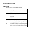
How to Read This Document.
■ Format of This Book
The explanation concerning the main term used in this book is shown as follows.
Term Meaning
I-bus It is a bus of the width of 16 bits for an internal instruction. Because the FR20 series has
adopted internal Harvard Architecture, the instruction and data are the independent
buses. The bus converter is connected with I-BUS.
D-bus It is a data bus of the width of the internal 32 bits. An internal resource is connected
with D-bus.
C-bus It is an internal multiplex bus. The C-bus connects to the I-bus and D-bus via the switch.
The external interface module is connected with C-BUS. The external data bus
multiplexes data and instructions.
R-bus It is a data bus of the width of the internal 16 bits. R-bus is connected with D-bus
through the adaptor.
Various I/O, the clock generation block, and the interruption controller are connected
with R-bus.
The R-bus is 16-bit width, so the address and data are multiplexed. If the CPU accesses
these resources, it takes a number of cycles.
E-unit It is an operation execution unit.
φ It is a system clock. It is a clock output from the clock generation block to the each
internal resource connected with R-bus. The system clock at the highest speed shows
the same cycle as source oscillation but is divided into 1, 1/2, 1/4, and 1/8 (or 1/2, 1/4,
1/8, and 1/16) by PCK1 and PCK0 of the clock generator GCR register.
θ It is a system clock. It is an operation clock of resource and CPU connected with buses
other than R-bus.
The system clock at the highest speed shows the same cycle as source oscillation but is
divided into 1, 1/2, 1/4, and 1/8 (or 1/2, 1/4, 1/8, and 1/16) by CCK1 and CCK0 of the
clock generator GCR register.