


92
CHAPTER 4 External Bus Interface
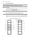
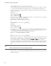
(AMR1 to AMR5) assumes "care" by "0" and "don't care" by "1".
"care" indicates the address space while setting "0" when the ASR set value is "0" or setting "1" when it is
"1". "don't care" indicates the address space for both "0" and "1" cases regardless of the ASR set value.
Examples for each chip select area specification by combining the area selection register and area mask
register are shown below.
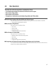
[example 1]
ASR1 = 00000000 000000 11
B
AMR1 = 00000000 000000 00
B
When the above is set, the AMR1 bit supporting the bit where "1" is set to ASR1 is "0", so the address
space of area 1 will be 64 KB as per the following.
00000000 00000011 00000000 00000000
B
(00030000
H
)
to
00000000 00000011 11111111 11111111
B
(0003FFFF
H
)
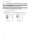
[example 2]
ASR2 = 00001111 11111111
B
AMR2 = 00000000 000000 11
B
When the above is set, "1" and "0" are left as "care" for the ASR2 set value supporting the bit where "0" is
set as AMR2, and the ASR2 bit supporting the bit where "1" is set as AMR2 will be "don't care" for "0" or
"1", so the address space of area 2 will be 256 KB as per the following.
00001111 11111100 00000000 00000000
B
(0FFC0000
H
)
to
00001111 11111111 11111111 11111111
B
(0FFFFFFF
H
)
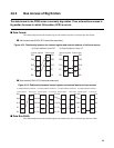
The address space of each area 1 to 5 can be arbitrarily allocated in units of at least 64 KB in the 4 GB
space by ASR1 to ASR5 and AMR1 to AMR5. Within the area specified by these registers, when bus
access is performed on area 1, the supported read/write pin (RD
, WR0, and WR1) will be "L" output.
As area 0, space other than the area set by ASR1 to ASR5 and AMR 1 to AMR5 is allocated, the area other
than 0001000
H
to 0005FFFF
H
is allocated by the initial values of ASR1 to ASR5 and AMR1 to AMR5 at a
reset.
Note:
Set the chip select area so that mutual overlapping is avoided.
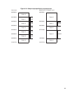
Figure 4.5-4 shows a map set in the units of 64KB by the initial value at a reset and a map of area set in the
example 1 and 2 above.