151
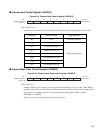
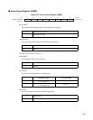
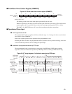
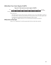
■ Drum Mask Timer Control Register (DRMMTC)
Figure 6.3-5 Drum mask timer control register (DRMMTC)
[bit7 to 0]:D7 to 0
The masking period control of the drum input is performed by the set value.
When Φ is specified as the clock cycle time selected by the mask timer clock select (CS) bit of the drum
control register, and N is specified as the set value, the drum input masking period TM is as follow.
TM= ΦMT × N ± ΦMT/2. However, N is set to 0, the mask processing does not perform.
■ Operation of Drum Input
●
4-bit Programmable divider
The programmable divider can perform division within the range 1 to 15 using the value set to the drum
input control register (DRMDVC).
Refer to the capstan input section for operation of the programmable divider.
Rewriting the DINV bit affects the programmable divider operation. Prior to perform rewriting, some kind
of action should be performed, such as masking the capture input.
●
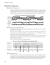
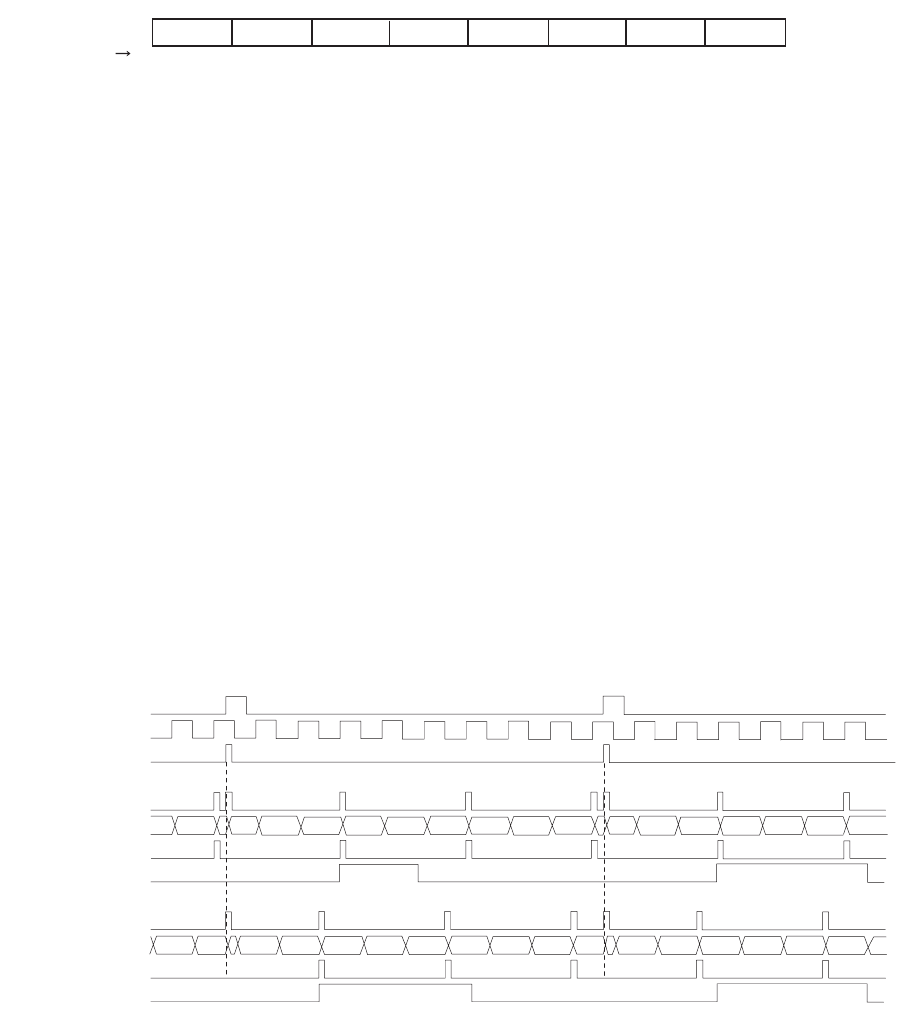
Initialization of programmable divider by DPG input
The programmable divider is initialized by the rising edge of the DPG input if DPG input is enabled.
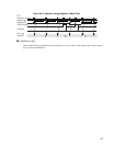
Figure 6.3-6 shows the initialization operation by DPG input and the set timing of DPG detection flag.
Figure 6.3-6 Timing diagram of initialization operation by DPG input
7 6 5 4 3 2 1 0
XXXX XXXX
B
Initial value
bit
D7 D6 D5 D4 D3 D2 D1 D0
R/W R/W R/W R/W R/W R/W R/W R/W
Access
Address: 000055
H
DPG input
DFG input
DPG Edge
Case1 (INV=0)
DVDFG output
DPG Flag
Case2 (INV=1)
DVDFG output
DPG Flag
2 1 3 2 1 3 2 1 3 2 1 3 2 1 3 2 1 3
2 1 3 2 1 3 2 1 3 2 1 3 2 1 3 2 1 3
Wclr Wclr
Wclr Wclr
Load timing
Counter value
Load timing
Counter value


