


12
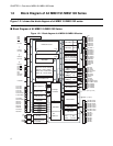
CHAPTER 1 Overview of MB91191/MB91192 Series
72
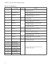
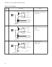
PC3/PWM4/SCS2
F
This pin is shared with PWM output and serial 2 chip select. It
is CMOS schmitt input.
73
PC2/PWM5/SCS1 This pin is shared with PWM output and serial 1 chip select. It
is CMOS schmitt input.
74
PC1/SCK0 This pin is shared with serial 0 shift clock.
It is CMOS schmitt input.
75
PC0/SO0
C
This pin is shared with serial 0 serial output.
It is CMOS input.
76
PD7/SI0
F
This pin is shared with serial 0 serial input.
It is CMOS schmitt input.
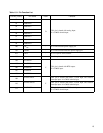
77
PD6/SCS0 This pin is shared with serial 0 chip select input.
It is CMOS schmitt input.
78
PD5/SCK1 This pin is shared with serial 1 shift clock.
It is CMOS schmitt input.
79
PD4/SO1
C
This pin is shared with serial 1 serial input.
It is CMOS input.
80
PD3/SI1/INT2
F
This pin is shared with serial 1 serial input and external
interrupt 2. It is CMOS schmitt input.
81
PD2/SCK2 This pin is shared with serial 2 shift clock.
It is CMOS schmitt input.
82
PD1/SO2
C
This pin is shared with serial 2 serial output.
It is CMOS input.
83
PD0/SI2
F
This pin is shared with serial 2 serial input.
It is CMOS schmitt input.
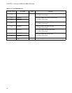
84 PA7/AN-F/KEY7
E
This pin is shared with analog input and key input.
It is CMOS schmitt input.
85 PA6/AN-E/KEY6
86 PA5/AN-D/KEY5
87 PA4/AN-C/KEY4
88 PA3/AN-B/KEY3
89 PA2/AN-A/KEY2
90 PA1/AN-9/KEY1
91 PA0/AN-8/KEY0
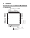
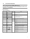
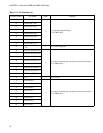
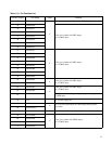
Table 1.5-1 Pin Function List
Pin No. (LQFP) Pin name Form Function