222
CHAPTER 13 External Interrupt
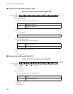
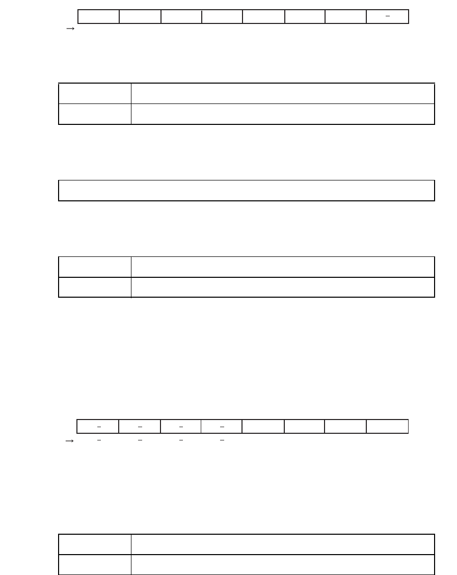
■ External Interrupt Enable Register (EIE)
Figure 13.3-3 External interrupt enable register (EIE)
[bit7 to 5]:INT2E to 0E
There are interrupt enable bits of INT2 to 0.
[bit4]:Test
It is test control bit.
[bit3 to 1]:I2CLR to I0CLR
There are interrupt flag clear bits of INT2 to 0.
The read value of this bit is always "1".
[bit0]:
It is an unused bit.
■ External Interrupt Request Flag (EIF)
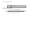
Figure 13.3-4 External interrupt request flag (EIF)
[bit7 to 4]:
It is an unused bit.
[bit3 to 1]:IF2 to 0
There are input edge detection flag of INT2 to 0.
[bit0]:Test
It is test bit.
7 6 5 4 3 2 1 0
0000 111-
B
Initial value
bit
Address: 000098
H
INT2E INT1E INT0E Test I2CLR I1CLR I0CLR
R/WR/WR/WR/WWWWW
Access
0 Interrupt interdiction
1 Interruption permission
Please set "0".
0 The flag is clear.
1 None
7 6 5 4 3 2 1 0
---- XXXX
B
Initial value
bit
Address: 000099H
RRRR
IF2 IF1 IF0
Test
Access
0 None
1 Falling edge detection


