


113
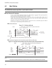
4.8 Program Example of External Bus Operation
A simple program example for operating the external bus is described.
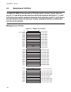
■ Program Specification Example of External Bus Operation
The setting of register is shown as follow.
●
Area
• Area 0 (AMD0) : 32-bit, usual bus, automatic wait 0
• Area 1 (AMD1) : 16-bit, time division I/O, automatic wait 2
• Area 2 (AMD32) : 32-bit, usual bus, automatic wait 1
• Area 3 (AMD32) : 32-bit, usual bus, automatic wait 1
• Area 4 (AMD4) :16-bit, DRAM, page size 256, 1CAS/2WE, with wait, CBR refresh
• Area 5 (AMD5) :16-bit, DRAM, page size 512, 2CAS/1WE, without wait, CBR refresh
●
The others
• Refresh (RFCR): without wait, 1/8 setting
• External pin (EPCR0): external RDY reception, arbitration of BRQ, BGRNTX
• External pin (DSCR) :DRAM pin setting
• Little endian (LER) : area 2
Note the following about the others.
• MD2, 1, and 0 are "010", and external vector is 32-bit mode.
• Before setting the mode register (MODR), set area 0 to the same bus width.
• Set the area 1 to 5 not to overlap.
■ Program Example of External Bus Operation
Under this program, bytes are used to write the byte register, and half-words are used for the half-word
register for explanatory purposes.
***** Example program *****
//Each register setting
init_gcr ldi:8 #0x00,r0 // gcr register X1 clock mode
ldi:20 #0x484,r1 // gcr register address setting
stb r0,@r1 // gcr register write
init_epcr ldi:20 #0xffff,r0 // External pin setting
// External RDY wait, bus arbitration by BRQ, BGRNTX
ldi:20 #0x628,r1 // epcr0 register address setting
sth r0,@r1 // epcr0 register write
init_dscr ldi:8 #0xff,r0 // DRAM pin setting
// RAS, CAS, WE
ldi:20 #0x625,r1 // dscr register address setting