


282
CHAPTER 21 Flash Memory
■
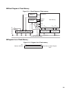
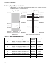
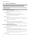
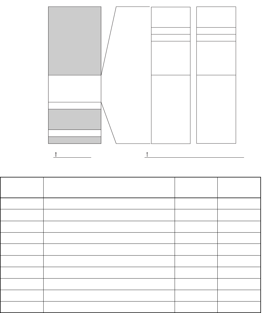
Memory Map and Sector Construction
Address mapping of the flash memory differs when accessed from the FR-CPU and by the ROM writer
*1
.
This shows the mapping at accessing from the CPU.
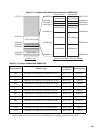
Figure 21.1-3 Memory map and sector construction (MB91F191A)
Table 21.1-1 Sector address table (MB91F191A)
Sector address Address range
Corresponding
bit position
Sector capacity
SA0 000A0000-1h to 000BFFFC-Dh (MSB side 16-bit) Bit31 to 16 64 Kbytes
SA1 000C0000-1h to 000DFFFC-Dh (MSB side 16-bit) Bit31 to 16 64 Kbytes
SA2 000E0000-1h to 000EFFFC-Dh (MSB side 16-bit) Bit31 to 16 32 Kbytes
SA3 000F0000-1h to 000F3FFC-Dh (MSB side 16-bit) Bit31 to 16 8 Kbytes
SA4 000F4000-1h to 000F7FFC-Dh (MSB side 16-bit) Bit31 to 16 8 Kbytes
SA5 000F8000-1h to 000FFFFC-Dh (MSB side 16-bit) Bit31 to 16 16 Kbytes
SA6 000A0002-3h to 000BFFFE-Fh (LSB side 16-bit) Bit15 to 00 64 Kbytes
SA7 000C0002-3h to 000DFFFE-Fh (LSB side 16-bit) Bit15 to 00 64 Kbytes
SA8 000E0002-3h to 000EFFFE-Fh (LSB side 16-bit) Bit15 to 00 32 Kbytes
SA9 000F0002-3h to 000F3FFE-Fh (LSB side 16-bit) Bit15 to 00 8 Kbytes
MSB side 16bit LSB side 16bit
SA4(16Kbyte) SA9(16Kbyte)
SA3(8Kbyte) SA8(8Kbyte)
SA2(8Kbyte) SA7(8Kbyte)
SA1(32Kbyte) SA6(32Kbyte)
Flash memory region
Internal RAM region
SA0(63Kbyte) SA5(63Kbyte)
Memory map Sector construction (SA=Sector address)
31 16 015
Status register
FFFFFFFFH
000FFFFFH
000C0800H
000C0000H
000007C0H
00000000H
000FFFFC-DH
000F8000-1H
000F4000-1H
000F0000-1H
000E0000-1H
000C0800-1H
000FFFFE-FH
000F8002-3H
000F4002-3H
000F0002-3H
000E0002-3H
000C0802-3H