


58
CHAPTER 3 CPU
■ Notes on Writing to Mode Register (MODR)
Before writing to the MODR, AMD0 to AMD5 must be set, and the bus width in each chip select (CS) area
must be decided.
The MODR has no bits used to set the bus width.
For the bus width, before writing to the MODR, the mode pins (MD2 to 0) are valid. After MODR writing,
set values (BW1, BW0) of the AMD0 to AMD5 will be valid.
For example, the external reset vector performs in the normal area 0 (the area in which the CSOX is active),
but in this case, the bus width is decided by the MD2 to MD0 pins. The bus width at that time is set to 32 or
16 bits by MD2 to MD0, and if MODR is written while nothing is set to AMD0, the initial value of the
AMD0 bus width has been set to 8 bits. So bus operation will be performed by transiting the area 0 to 8 bit
bus mode after writing the MODR, and erroneous operation will result.
AMD0 to AMD5 must be set before writing the MODR to prevent this kind of problem.
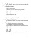
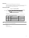
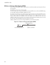
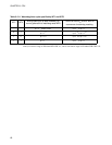
Figure 3.11-2 Notes on writing to mode register (MODR)
RST (Reset)
MODR programming
Bus width setting: MD2, 1, 0 BW1, 0 of MD0-5A