


32
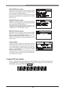
DVD Multitrack Recorder DV824DVD Multitrack Recorder DV824
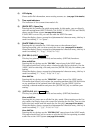
DVD Multitrack Recorder DV824DVD Multitrack Recorder DV824
DVD Multitrack Recorder DV824
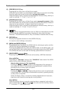
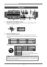
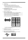
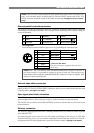
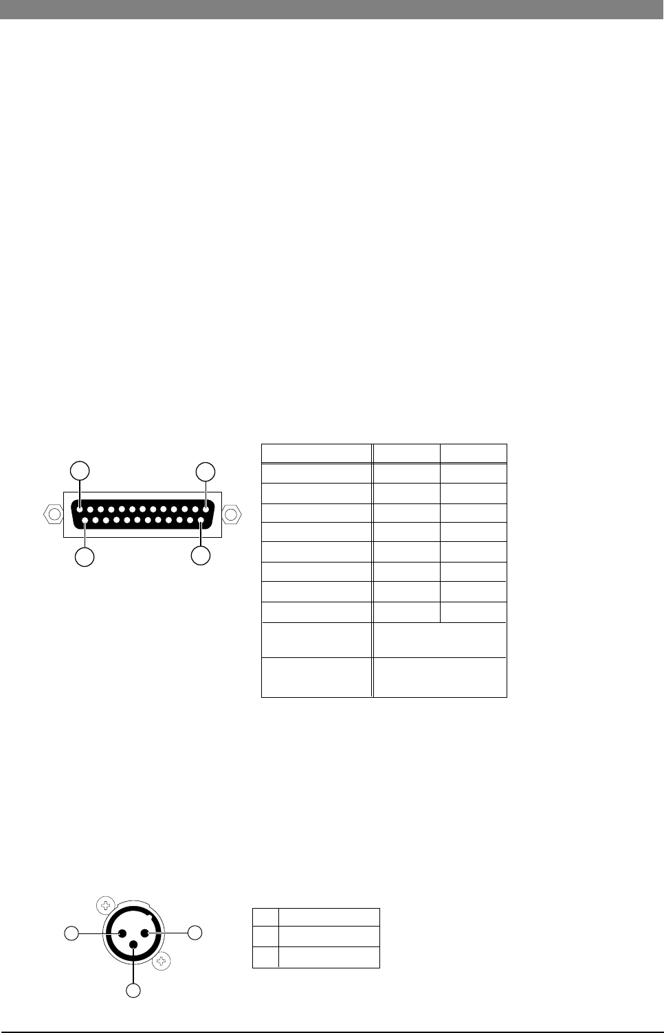
11) [DIGITAL I/O AES/EBU] connector
This connector inputs and outputs AES/EBU or S/P DIF digital signals.
You can set the digital input channel by the "Setup Digital In" menu item of the
"SYS SETUP" menu in the MENU mode (see page 119 for details).
The unit automatically detects the digital input signal format.
The digital output signal format can be set by the "Digital out" menu item of the
"SYS SETUP" menu in the MENU mode (see page 120 for details).
The connector type is D-sub 25-pin.
Signal
1
2
3
4
5
6
7
8
Open
1
14
13
25
Hot
Cold
14
15
16
17
18
19
20
21
Frame GND
Output 7/8
Output 5/6
Output 3/4
Output 1/2
Input 7/8
Input 5/6
Input 3/4
Input 1/2
9, 11
10, 12, 13, 22, 23
24, 25
* The connector pin assignment is compatible with the D-sub 25-pin
connectors on YAMAHA equipment.
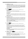
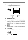
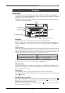
13) [ANALOG OUTPUT BALANCED] connectors
These connectors output analog audio signals of tracks 1 through 8.
The connector type is XLR-3-32 (balanced/+4dBu).
1
2
3
GND
HOT
COLD
3
2
1
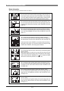
10) [WORD IN]/[WORD OUT] connector
The [WORD IN] connector receives a word clock signal.
The [WORD OUT] connector feeds word clock signal.
The connector type is BNC.
12) [WORD IN] terminate switch
Terminates the word input signal by setting the switch to “ON”.
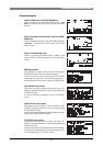
9) [ETHERNET] port
This port is used to connect to the Ether network.
The connector type is RJ45 (conformed to 100/10BASE-T FTP).
The LINK and TX/RX indicators light in the following conditions.
• The LINK indicator lights when the unit recognizes the network.
• The TX/RX indicator flashes when the unit is sending or receiving data.