


18
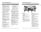
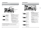
2-2 SUB PANEL
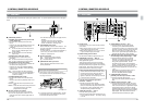
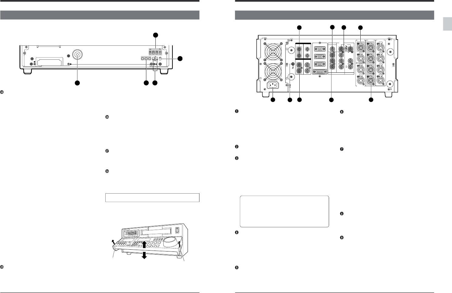
The sub panel can be accessed by opening the operation panel. To open the operation panel, refer to the figure
below.
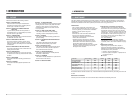
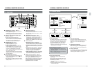
[TIME CODE] switches
Ⅲ [DF/NDF] drop frame/non-drop frame mode
switch (NTSC only)
● To set the time code drop frame/non-drop
frame.
* Effective only when the [INT/EXT] switch is set
to “INT” and the [PRESET] switch is set to
“PRESET”.
DF: To write the time code in the Drop Frame
mode. The [DF] indicator lights on the
counter display.
NDF: To write the time code in the Non-drop
Frame mode.
Ⅲ [INT/EXT] time code select switch
● To select internal or external time code
generation.
INT: To use the internal time code generator.
EXT: To use an external time code generator.
Ⅲ REC/FREE Run mode select switch
● To select one of two Run modes available with
the internal time code generator.
* Effective only when the [PRESET/REGEN]
switch is set to “PRESET” and the [INT/EXT]
switch to “INT”.
REC: Time code runs only during recording.
FREE: Time code runs in real time regardless of
the VCR’s operating mode. Select this
position for editing.
Ⅲ PRESET/REGEN select switch
● To select the Internal Time Code Generator
mode.
* Effective only when the [INT/EXT] switch is set
to “INT”.
PRESET: Select this mode to preset time code
data.
REGEN: Select this mode when using the internal
time code generator in sync with a
playback time code signal.
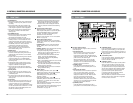
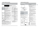
[CF] color frame servo switches
Use to switch the color frame servo ON/OFF.
● For the PAL signal system, select the 4 or 8
field color frame servo with the [4/8] switch on
the side.
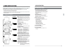
How to open the operation panel
2 CONTROLS, CONNECTORS AND DISPLAYS
● Lift the bottom edge of the panel to open it.
The operation panel can be locked in 6 steps in
the range of 0 to 90˚.
Lock release lever
Lock release lever
● To return the panel to its original position, pull the
lock release levers in the direction shown by the
arrows and push down the panel.
SERVICE USE ONLY
OFF
RF
HID GND
8
ON
ON
4
OFF
TIME CDOE
INT
FREE
PRESET
EXT
DF
NDF
REC
REGEN
ON SCREENCF
(625)
38
37
35
34
36
● For the NTSC signal system, the [4/8] switch is
disabled.
* To set the color frame servo with these
switches, set menu switch No. 008 <CAP
LOCK> to “SW SEL”. (See page 105)
[ON SCREEN] select switch
Use to switch the on-screen menu ON/OFF. The
on-screen information is output from the [LINE-2
SUPER] connector.
*If menu switch No. 513 <EDIT ON SCREEN> is
set to “ON”, you cannot turn the on-screen
display off. (See page 24)
Service connectors
[RF] ... RF test signal output connector
[HID] ... Trigger signal output connector
[G] ... Ground connector
[SERVICE USE ONLY] connector
Used to diagnose malfunctions and for other
service procedures.
19
2 CONTROLS, CONNECTORS AND DISPLAYS
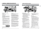
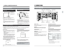
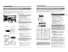
2-3 REAR PANEL
2
5
IN
CH1 /2
CH1 /2
CH3 /4
CH3/4
OUT
IN OUT
1
2
Y
Y
R-Y
B-Y
B-Y
R-Y
IN
OUT
OUT
OFF
ON
75
LINE1
LINE2
SUPER
RS- 232C
COMPOSITE
LINE IN
REF
COMPONENT
COMPOSITE
REMOTE IN (9P)
REMOTE OUT (9P)
VIDEO CONTROL
CH1
CH2
CH3
CH4
CH2
CH3
CH4
CH1
IN
OUT
L
R
SERIAL V / ASERIAL V / A
AES / EBUAES / EBU
VIDEO
TIME CODE
AUDIO IN
AUDIO OUT
AUDIO MONITOR
9
8
7
6
1
3
4
[TIME CODE IN] connector ... XLR
● Accepts external LTC time code signals
conforming to the SMPTE/EBU standard.
Connect this connector to an external time code
generator. A signal containing a large amount of
jitter cannot be used for LTC time code. Be
sure to use a regenerated signal (stable signal
matched with the phase of video signals).
[REF IN] external sync signal input connector/
75 terminating switch (loop-through) .... BNC
● Accepts external reference sync signals.
Because of its loop-through design, this
connector can distribute signals to other units
through the opposite terminal. Set the
terminating switch to OFF when distributing
signals. If signal distribution is not desired or is
terminated at this unit, set the switch to ON.
● Does not accept signals with an input level over
1 Vp-p.
* When setting up an editing system, input a
black burst or standard color signal to
this unit. The [GEN] indicator will light.
[COMPOSITE IN] connectors
[LINE IN] video line input connector ...BNC
● Accepts composite video signals.
Input composite signals passed through the
TBC.
[SERIAL V/A IN] connectors ... BNC
● Accepts serial video/audio signals. The lower
connector is an active loop through connector.
If the VCR is not turned on, no signal will be output.
Serial signals cannot be input if the optional
SA-D95U digital interface board is not installed.
Always input external sync signals when inputting
digital signals. Both video and audio must be
synchronized with the external sync signal.
[AC IN] socket
Connect to an AC power outlet via the provided
power cable.
● When usage voltage is 120 V or less; use the
A-type (flat-pin type) power cable.
● When usage voltage is 127 V or over; use the
C-type (round-pin type) power cable.
[SIGNAL GND] ground terminal
This terminal is a GND for signals among unit.
[AES/EBU IN] connector .... BNC x 2
Accepts digital audio interface standard (AES/
EBU) digital audio signals.
These signals cannot be input if the optional
SA-D95U digital interface board is not installed.
Always input external sync signals when inputting
digital signals. Both video and audio must be
synchronized with the external sync signal.
When the serial digital inputs and outputs of
several VCRs are connected in series, do not
input the same signal to each VCR as they
may not be input correctly. Digital audio
signals, in particular, will not be input correctly
to the next VCR in the series.
[Y.R-Y.B-Y IN] component signal input
connector .... BNC x 3
● Accepts component video signals.
Set menu switch No. 104 <CPN LEV./SETUP
(525)> to select MII (LOW), Bcam (HIGH) and
the presence of setup signals (NTSC only).
The default setting is Bcam with setup.
[AUDIO IN] connector .... XLR x 4
● Accepts analog audio signals.
● Set the input level with menu switches No. 224
to 227 <AUDIO IN LEVEL>. The factory setting
is +4 dB.