


90
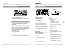
9 OTHER FUNCTIONS
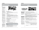
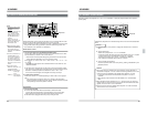
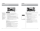
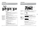
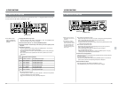
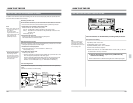
More than one BR-D95U can be operated at the same time with one RS-422 serial remote controller.
9-pin remote connector
RS-422 serial remote controller
9-pin remote cable
First VCR
REMOTE OUT
Second VCR
REMOTE OUT
Last VCR
REMOTE IN
REMOTE IN
IN
CH1/2
CH1/2
CH3/4
CH3/4
OUT
IN OUT
1
2
Y
Y
R-Y
B-Y
B-Y
R-Y
IN
OUT
RS-2 32C
COMPOSITE
LINE IN
COMPONENT
REMOTE IN (9P)
REMOTE OUT (9P)
VIDEO CONTROL
SERIAL V / ASERIAL V / A
AES / EBUAES / EBU
VIDEO
IN
CH1/2
CH1/2
CH3/4
CH3/4
OUT
IN OUT
1
2
Y
Y
R-Y
B-Y
B-Y
R-Y
IN
OUT
RS-2 32C
COMPOSITE
LINE IN
COMPONENT
REMOTE IN (9P)
REMOTE OUT (9P)
VIDEO CONTROL
SERIAL V / ASERIAL V / A
AES / EBUAES / EBU
VIDEO
IN
CH1/2
CH1/2
CH3/4
CH3/4
OUT
IN OUT
1
2
Y
Y
R-Y
B-Y
B-Y
R-Y
IN
OUT
RS-2 32C
COMPOSITE
LINE IN
COMPONENT
REMOTE IN (9P)
REMOTE OUT (9P)
VIDEO CONTROL
SERIAL V / ASERIAL V / A
AES / EBUAES / EBU
VIDEO
9-3 SIMULTANEOUS OPERATION
With a remote controller
that requires the VCR to
reply to commands, set
menu switch No. 369
<PARA RUN> to “OFF”
for the first VCR, and
“ON” for the second and
subsequent VCRs.
*The recorder's variable
playback speed is -1.0x
to +1.0x. The player’s
variable playback speed
is -2.0x to +3.0x.
Connection
Connect the 9-pin remote connector of the RS-422 serial remote controller to the
first VCR’s [REMOTE IN] connector.
Connect the first VCR’s [REMOTE OUT] connector to the second VCR’s
[REMOTE IN] connector with a 9-pin remote cable, the second VCR’s [REMOTE
OUT] connector to the third [REMOTE IN] connector, and so on.
Setting
Set the all connected VCRs as follows.
• Set menu switch No. 369 <PARA-RUN> to “ON (1)”.
• Press the front panel [REMOTE] button to engage the VCR in the Remote mode
(the “REMOTE” indicator lights on the display).
Operation
• Recording, playback, fast-forward and rewind on all the VCRs can be controlled
at the same time with the RS-422 serial remote controller.
Simultaneous operation with the BR-D95U
When the BR-D95U is used instead of the RS-422 serial remote controller, set as
follows.
Ⅲ BR-D95U used for simultaneous operation (first VCR)
• If you want to operate the first VCR at the same time, set menu switch No. 369
<PARA-RUN> on the first VCR to “ON (1)”. If not, set to “OFF (0)”
• Set the operation mode to “Local”. Press the [REMOTE] button so that the
“REMOTE” indicator on the display goes out.
Ⅲ Second VCR
• Set menu switch No. 369 <PARA-RUN> to “OFF (0)”.
• Set the operation mode to “Remote”.
Ⅲ Third and subsequent VCRs
• Set menu switch No. 369 <PARA-RUN> to “ON (1)”.
• Set the operation mode to “Remote”.
Operation
When the [PLAYER] button is pressed...
• If menu switch No. 369 <PARA-RUN> on the first VCR is set to “OFF (0)”;
[ The [PLAYER] button is illuminated.
• If menu switch No. 369 <PARA-RUN> on the first VCR is set to “ON (1)”;
[ The [PLAYER] and [RECORDER] buttons are illuminated.
Any operation executed on the first VCR will automatically be executed on all the other
VCRs as well.
91
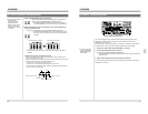
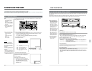
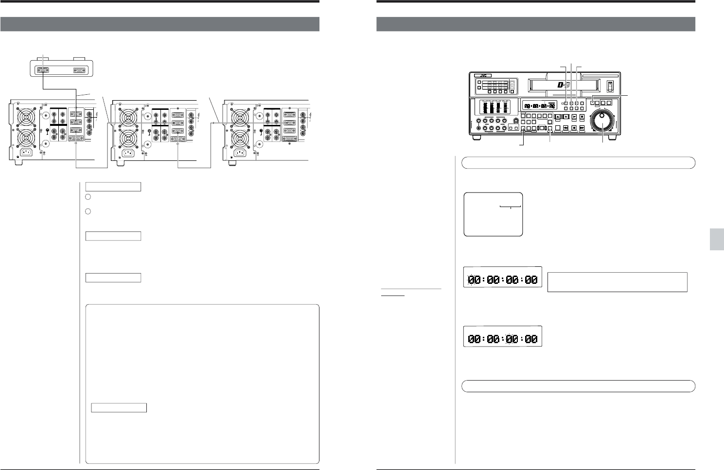
9-4 FIXED TIME CUE UP FUNCTION
The tape can be cued to the position whose time data (fixed time) is recorded with “00F: FIXED TIME ENTRY” on
the top menu page (fixed time cue up function). Useful to cue up the tape to a specified position.
9 OTHER FUNCTIONS
● Checking the registered
time data
The registered time data
can be checked on screen
by displaying “00F: FIXED
TIME ENTRY”. Press the
[HOLD] button to display
the registered time data on
the counter display.
● In the Fixed Time Register-
ing mode, press the
[RESET] button to reset to
“00:00:00:00”.
00E:OPTIMUM REC CURRENT
00F:FIXED TIME ENTRY
00:00:00:00
Registering the fixed time data
1. Press the [MENU] button to display the menu setting screen.
2. Turn the jog dial to select the top menu “00F: FIXED TIME ENTRY”.
• The time data currently registered is shown on screen.
3. Press the [HOLD] button.
[ The Fixed Time Data Registering mode is engaged and the time data
currently registered is shown on the counter display.
The uppermost digit blinks.
* The time data does not blink on screen.
Register the time data on the counter display.
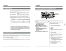
Fixed time cue up operation
1. Load a recorded tape.
2. Select the counter display mode with the [COUNTER] button.
• “TC” or “UB”: The tape is cued up according to the time code registered on the
tape.
• “CTL”: The tape is cued up according to the time data shown on the CTL
counter.
3. Press the [PREROLL] button while pressing the [SHIFT] button.
The tape is cued up to the registered position.
4. Turn the jog dial to select the digit.
The selected digit blinks.
5. Set the time data by turning the jog dial while pressing the [SEARCH] button.
6. Repeat steps 4 and 5 to set the value for each digit.
7. When setting is complete, press the [SET] button.
“SET” is shown on the counter display.
The set time data is registered and the normal screen is restored.
Time data
POWER
ON
I
OFF
O
M
H
F
S
REC
MENU
PLAY
PAUSE/ STILL
REW
STOP
FF
EJECT
PHONES
CH1
CH2
CH3
CH4
REC
PLAY
PULL FOR VARIABLE
TRACKING
CH1
CH1
CH2
CH3
CH4/
TRACKING
SET
HOLD
PB
PB/EE
COUNTER
UB
CONDITION
AUDIO
INPUT
VIDEO
INPUT
AUDIO
MONITOR
PULL
RELEASE
RESET
VCON
REMOTE
TOP VIDEO AUDIO
OTHERSON SCREENTIME CODESERVO/SYS
USER
INSERT
STAND BY
PLAYER
SEARCH
VAR
P.PLAY
DA3
DA2
DA1VIDEO
ASSEM
IN
ENTRY
OUT
CANCEL
SHIFT
REVIEW
METER MODE
TRACKING
FINE
PREVIEW
AUTO EDIT
PREROLL
TC
RECORDER
DA4
VIDEO CASSETTE RECORDER
BR-D95U
STILL
X-1
REV
FWD
X1
CH2
CH3
CH4
CH1
CH2
CH3
CH4
CH1
CH2
CH3
CH4
SIF
SDI
AES/EBU
AUDIO INPUT / AUDIO MONITOR SELECT
LINE
CPN
L
ANALOG
R
PULL
RELEASE
CTL
P.READ
AUTO
OFF
V.VAR
REMOTE
PB/EE
16:9
TC
UB
DF
SERVO
GENCF
AP
525
OVER
–60
–2
–4
+2
+4
0
–40
–30
–20
–10
0
dB
dB
R P
OVER
–60
–2
–4
+2
+4
0
–40
–30
–20
–10
0
dB
dB
R P
OVER
–60
–2
–4
+2
+4
0
–40
–30
–20
–10
0
dB
dB
R
P
OVER
–60
–2
–4
+2
+4
0
–40
–30
–20
–10
0
dB
dB
R
P
625
Variable Motion
COMPONENT DIGITAL
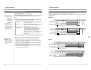
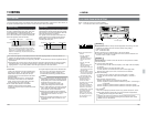
[SET] button
[HOLD] button[COUNTER] button
[PREROLL] button Jog dial
[SEARCH] button
[SHIFT] button
● 00A: MENU in the top
menu
Even though INITIAL is
selected for SETTING,
registered data is not reset.