


132
13-2 RS-232C Commands
13 RS-232C protocol
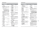
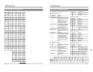
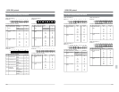
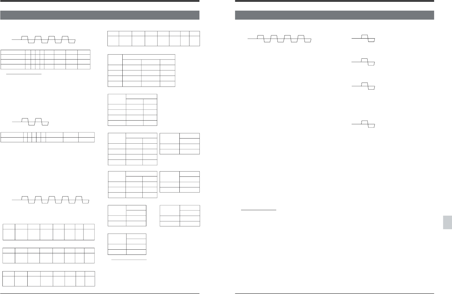
TxD E9 3* 3* 3*
RxD 0A 0A 0A 0A
TxD EB 3*
RxD 0A 0A
Fifth byte (DATA3)
76 5 43210
IS IS IS IS MON CF CF PB
CH2 1 CH2 0 CH1 1 CH1 0 /IPT SW FLD /EE
VIDEO INPUT SELECT
Setting
Bit name
VID GEN DIG VID LINE
CPN 0 0 0
LINE 0 0 1
SIF 0 1 —
Internal 1 — —
AUDIO INPUT SELECT
Setting
Bit name
IS**1 IS**2
ANA 0 0
AES/EBU 0 1
SDI 1 —
Internal 1 1
AUDIO MONITOR SELECT
Setting
Bit name
MS**L MS**R
OFF 0 0
R CH 0 1
L CH 1 0
L+R CH 1 1
COUNTER
Setting
Bit name
UB TC
CTL 0 0
TC — 1
UB 1 0
PB PB/EE
Setting
Bit name
PB/EE
PB/EE 0
PB 1
REMOTE
Setting
Bit name
Rem/9pin
REMOTE 1
LOCAL 0
Auxiliary commands
• [56: Clear] and [41: ClearError] are invalid.
• [40: Enter] is invalid.
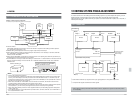
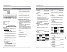
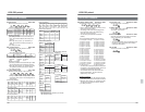
E9: Edit Preset 2 Basic Table
Selects the Edit mode for 4 channels.
• Each bit is defined as follows:
76543 2 1 0
First byte 0 0 1 1 0 INS ASM Video
Second byte 0 0 1 1 0 TC Aud2 Aud1
Third byte 0 0 1 1 DA4 DA3 DA2 DA1
Auxiliary commands
• [56: Clear] is valid for the second TxD byte or
later. All commands back to the first byte are
cleared.
• When [02: Error] occurs, [41: ClearError] is
valid. The previous command (one byte) is
cleared.
• [40: Enter] is invalid.
EB: TC Switch Preset Basic Table
Switches the time code generator function.
• Each bit is defined as follows:
765432 1 0
The first byte 0 0 1 1 0 REC RUN REGEN EXT
• REC RUN : 1: Rec Run 0: Free Run
REGEN : 1: Regene 0: Preset
EXT : 1: Ext 0: Int
Auxiliary commands
• [56: Clear] is valid for the second TxD byte or later.
All commands back to the first byte are cleared.
• When [02: Error] occurs, [41: ClearError] is valid.
The previous command (one byte) is cleared.
• [40: Enter] is invalid.
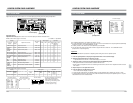
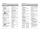
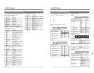
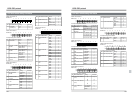
EC: Panel Switch Preset JVC-1 Table
Switches various settings on the front panel.
• Settings are defined with the input values for the
second TxD byte or later. The bit assignment is
shown below.
Second byte (DATA0)
76543210
MS MS MS MS VID DIG LINE
CH4 L CH4 R CH3 L CH3 R GEN VID
Third byte (DATA1)
76543210
MS MS MS MS UB TC
CH2 L CH2 R CH1 L CH1 R
Fourth byte (DATA2)
76543210
IS IS IS IS Rem
CH4 1 CH4 0 CH3 1 CH3 0 /9pin
TxD EC ** ** ** **
RxD 0A 0A 0A 0A 0A
Setting
Bit name
MON/IPT
MONITOR 0
INPUT 1
AUDIO INPUT/AUDIO
MONITOR
Setting
Bit name
CF SW
CF OFF 0
CF ON 1
CF ON/OFF SW
Setting
Bit name
CF FLD
4 FIELD 0
8 FIELD 1
8 FIELD: (625) only
CF 4/8 SW
133
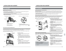
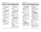
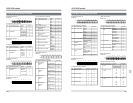
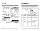
ED: Memory Switch Preset Basic/JVC-1 Table
Rewrites the contents of the menu switch.
• Refer to “Menu Switch Setting” to find out more
about menu switch contents.
• The setting of the menu switch changed with
this command is reset to the default setting
when the VCR is turned OFF.
• The second byte expresses the address
(Data0).
The corresponding addresses are as follows.
01 :Servo/System-1 information 08:System-2 information
10 :System-3 information 20:System-4 information
40 :System-5 information 88:System-6 information
89 :System-7 information 90:System-8 information
87 :System-9 information 09:System-10 information
91 :System-11 information 92:System-12 information
94 :System-14 information
0a :Video information-2 0b:Video information-3
0c :Video information-4 0d:Video-5 information
1b :Video-6 information 0e:Video-7 information
1e :Video-8 information 1c:Video-9 information
0f :Video-10 information 1f :Video-11 information
1d :Video-12 information 05:Audio-2 information
06 :Audio-3 information 07:Audio-4 information
03 :Audio-5 information 30:Audio-6 information
31 :Audio-7 information 80:TimeCode-1 information
81 :TimeCode-2 information 79 : TimeCode-3 information
77 :TimeCode-4 information 78:TimeCode-5 information
82 :OnScreen-1 information 83: OnScreen-2 information
84 :TBC information-1 86:TBC information-3
• The third and fourth bytes express individual bit
information for the specified address. These are
expressed as Data1/Data2 information.
• The rewritten data can be checked with D3:
MemorySwitchSense. The D3 command
applies only to JVC Table-1.
Auxiliary commands
• When [02: Error] occurs, [56: Clear] is valid. All
commands back to the first TxD byte are cleared.
• When [02: Error] occurs, [41: ClearError] is valid.
The previous command (one byte) is cleared.
• [40: Enter] is invalid.
TxD ED ** ** **
RxD 0A 0A 0A 0A
13-2 RS-232C Commands
13 RS-232C protocol
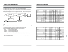
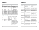
TxD FB
RxD 0A
TxD FA
RxD 0A
TxD F7
RxD 0A
TxD F6
RxD 0A
F6: JVC Table-1 On Basic/JVC-1 Table
Use the JVC Table-1 commands.
F7: Basic Table On Basic/JVC-1 Table
Use the Basic Table commands.
JVC Table-1 is set to OFF.
FA: Rec/DubRequest Basic/JVC-1 Table
Send this command before sending commands
such as [CA: REC], [CB: RECPause].
• The recording standby mode is maintained until
the REC or STOP command or Error release
command is transmitted.
FB: VTR IND Basic/JVC-1 Table
Checks that a VCR is connected.