


26
IN
CH1/2
CH1/2
CH3/4
CH3/4
OUT
IN OUT
1
2
Y
Y
R-Y
B-Y
B-Y
R-Y
IN
OUT
OUT
OFF
ON
75
LINE1
LINE2
SUPER
RS- 232C
COMPOSITE
LINE IN
REF
COMPONENT
COMPOSITE
REMOTE IN (9P)
REMOTE OUT (9P)
VIDEO CONTROL
CH1
CH2
CH3
CH4
CH2
CH3
CH4
CH1
IN
OUT
L
R
SERIAL V / ASERIAL V / A
AES / EBUAES / EBU
VIDEO
TIME CODE
AUDIO IN
AUDIO OUT
AUDIO MONITOR
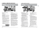
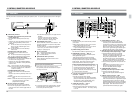
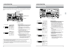
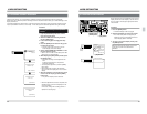
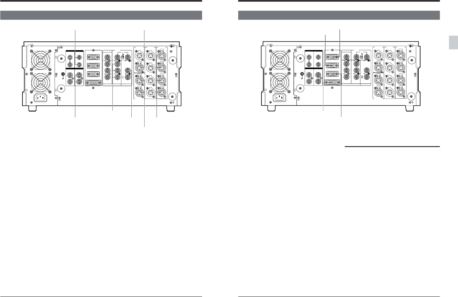
3-2 OUTPUT CONNECTIONS
[TIME CODE OUT][SERIAL V/A OUT]
[AUDIO OUT]
[AES/EBU OUT]
[COMPONENT OUT]
Set the component output level with menu switch No.
104 <COMPONENT LEVEL>.
● All video parameter settings except SCH phase can
be adjusted. (See page 119.)
[AES/EBU OUT]
Install the optional SA-D95U digital interface board to
output signals from this connector.
[AUDIO MONITOR]
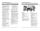
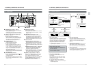
3 CONNECTIONS
[COMPONENT OUT]
[COMPOSITE OUT]
[SERIAL V/A OUT]
Install the optional SA-D95U digital interface board to
output signals from this connector.
● All video parameter settings except SCH phase can
be adjusted. (See page 119.)
[AUDIO OUT]
Set the audio output reference level with menu
switches No. 228 to 231 <AUDIO OUT LEVEL>.
[TIME CODE OUT]
Select the time code output method during search
with menu switch No. 452 <SEARCH LTC>.
[AUDIO MONITOR]
Set the audio output reference level with menu
switches No. 232 and 233 <AUDIO MON LEVEL>.
[COMPOSITE OUT]
● On-screen data is output only to the [LINE 2 -
SUPER] connector.
● Select the main time code or sub time code to
output VITC with menu switch No. 451 <VITC OUT
SELECT>.
● Video parameters can be adjusted. (See page 119.)
27
IN
CH1/2
CH1/2
CH3/4
CH3/4
OUT
IN OUT
1
2
Y
Y
R-Y
B-Y
B-Y
R-Y
IN
OUT
OUT
OFF
ON
75
LINE1
LINE2
SUPER
RS- 232C
COMPOSITE
LINE IN
REF
COMPONENT
COMPOSITE
REMOTE IN (9P)
REMOTE OUT (9P)
VIDEO CONTROL
CH1
CH2
CH3
CH4
CH2
CH3
CH4
CH1
IN
OUT
L
R
SERIAL V / ASERIAL V / A
AES / EBUAES / EBU
VIDEO
TIME CODE
AUDIO IN
AUDIO OUT
AUDIO MONITOR
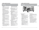
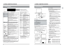
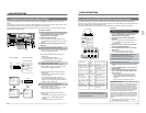
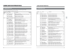
3-3 CONTROL SYSTEM CONNECTIONS
3 CONNECTIONS
[REMOTE IN (9P)]
Connect an editing control for the RS-422 serial
interface.
Editing controller menu setting switches are available.
Menu switch No. 359 <JOG FEELING>
Menu switch No. 363 <CONTROLLER SELECT>
To control more than one VCR at the same time, set
menu switch No. 369 <PARA-RUN> to “ON”.
[RS-232C]
Connect to an RS-232C interface in a personal
computer or other control unit.
[REMOTE OUT (9P)]
Connect another VCR with an RS-422 interface. You
will be able to control the other VCR from this unit.
To control more than one VCR at the same time,
connect this connector to a [REMOTE IN] connector
of the subsequent VCR.
[VIDEO CONTROL]
Connect an optional TBC remote control to operate
the built-in TBC video controls. The RM-G22U
cannot be connected.
When adjusting with a video controller, press the
[VCON] button to select “Remote” and activate the
settings. (Refer to “EDITING SYSTEM PHASE
ADJUSTMENT” on page 117.)
Editing remote control connection
● Set the editing timing to -7 frames from the editing
remote control.
● The preroll time should be set to 5 seconds or
more.
● When using the RM-G820U or RM-G870U editing
remote controller, execute the editing controller's
learn function before operating. Otherwise, the
number of retries will be increased.
● When the RM-G820 remote controller is connected
to this unit, set the menu switch No. 317 < 9PIN
DEVICE ID > to “JVC D80”. The remote controller’s
edit timing is automatically set to -7 frames.
[REMOTE IN (9P)]
[RS-232C]
[REMOTE OUT (9P)]
[VIDEO CONTROL]