


22
M
H
F
S
CONDITION
CTL
P.READ
AUTO
OFF
V.VAR
REMOTE
PB/EE
16:9
TC
UB
DF
SERVO
GENCF
AP
525
625
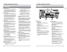
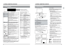
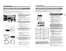
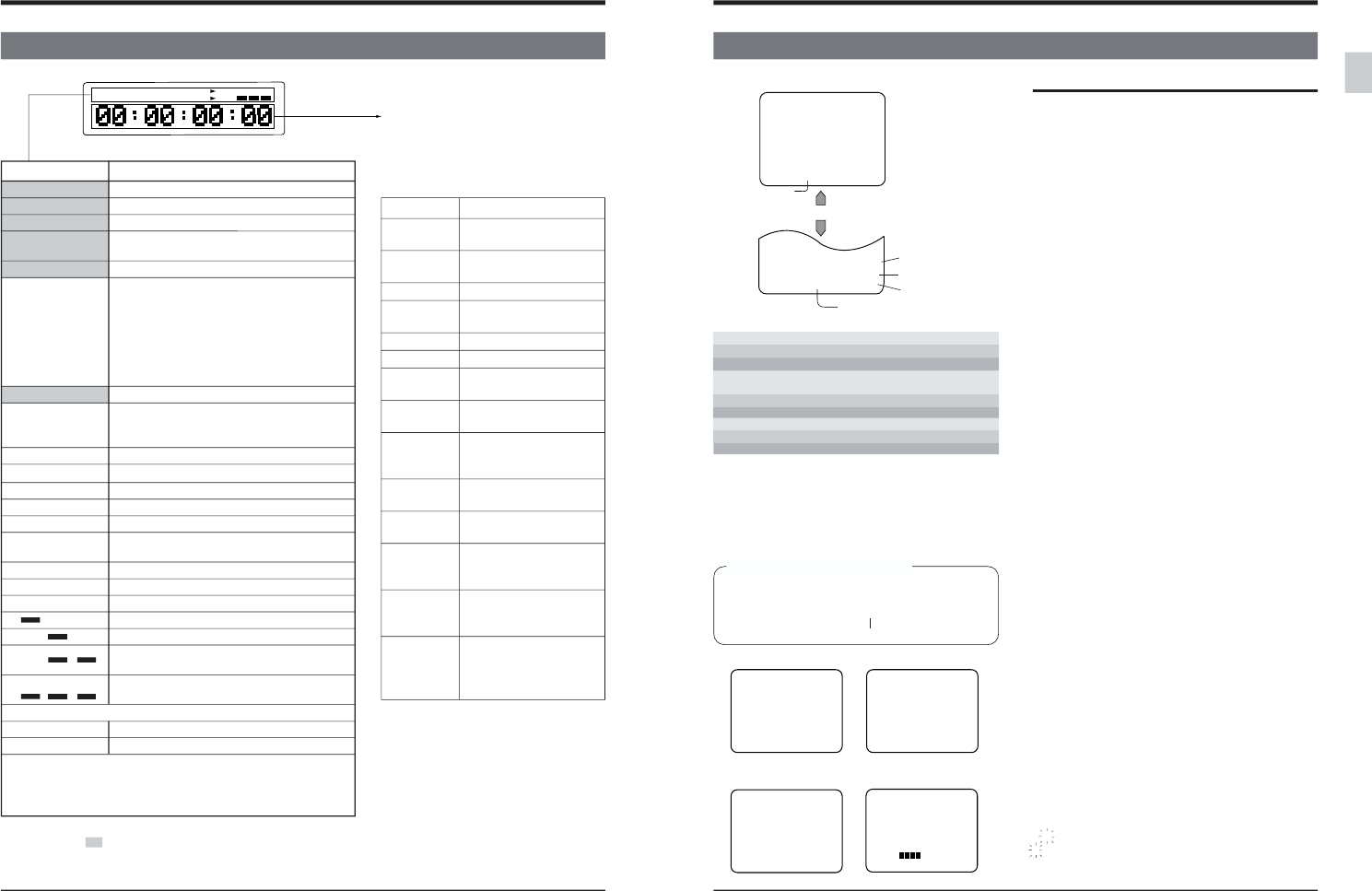
2-4 COUNTER DISPLAY
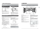
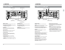
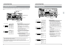
2 CONTROLS, CONNECTORS AND DISPLAYS
Indicator section
[VCON] button
* During swap editing, player information is shown only by the
indicators in the section when the player is selected. The [AUTO
OFF] indicator always shows recorder information.
Indication Meaning when lit
CTL The CTL counter is shown.
TC The time code is shown.
UB The user bits are shown.
DF The CTL counter or time code is in the
drop-frame mode. (525)
SERVO Servo is stable.
CF The color frame servo is set. This
indication lights during recording. When
the [CF] switch is ON and a tape with color
frame information is played back, this
indication also lights.
When the PLAYER is selected during
SWAP editing, the [CF] indication does not
light.
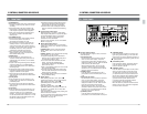
GEN Signals are input to the [REF] connector.
(Blinking) GEN The input digital audio signals cannot be
recorded correctly because no external
sync signal is input.
16:9 Wide aspect ID signal is being played back.
AP A non-D-9 tape is played back.
AUTO OFF A malfunction or abnormality has occurred.
P. READ The VCR is in the Pre-read mode.
V. VAR The video parameters can be adjusted.
PB/EE The PB/EE Auto Switching mode is
selected.
PB The PB mode is selected.
REMOTE The VCR is in the Remote mode.
CONDITION
Channel condition is normal.
Minor errors.
Major errors. Normal playback is not
possible.
(Blinking) Tracking is not correct.
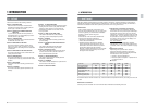
Video signal system
4
525 The NTSC signal system is set.
4
625 The PAL signal system is set.
The video signal system can be set with menu switch No. D95
<525/625> (on the top menu). After selecting the video signal
system, turn this unit OFF then ON again to switch to the
selected video signal system.
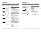
The following error messages may be
displayed during swap editing.
Indication Meaning
Local The player’s Local/
Remote is set to “Local”.
No Tape No cassette is loaded in
the VCR.
Bump Error Bump error occurs.
No Edit Cmd The edit mode is not
selected.
Dur = 0 Duration is set to 0.
Servo Error Servo error occurs.
Split No A. The audio insert mode is
not selected.
Rec Inh Recording is not possible
on this cassette.
IN/OUT Rev The IN and OUT points
are reversed in terms of
the timeline.
Over 300% Tape speed is more than
3x.
Over -200% Reverse tape speed is
more than -2x.
VTR No Play The VCR will not
function.During editing,
the VCR stops.
AuCondition Editing was interrupted
because of audio
conditions deteriorated.
NO CTL Stops the operation when
insert editing is executed
in a non-recorded
section.
●
Press the [STOP] button to release
error display indications.
●
“No Tape” indication goes out when a
cassette tape is loaded.
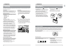
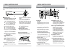
Video/audio control display
* For adjustment of each item, refer to
“Video control adjustment” on page 118.
23
E Ⅵ Ⅵ Ⅵ Ⅵ F Remaining time of 15 minutes or more
E Ⅵ Ⅵ Ⅵ Remaining time of less than 15 minutes
E Ⅵ Ⅵ Remaining time of less than10 minutes
E Ⅵ Remaining time of less than 5 minutes
E Ⅵ
(blinking)
Remaining time of less than 2 minutes
E
(blinking)
Remaining time of less than 1 minutes
No indication The remaining time is being calculated.
PLAY
R: TCR00:00:00:01
STOP
TCR
00:00:00:00
SUB TCR
00:00:00:00
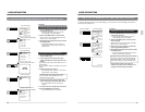
2 CONTROLS, CONNECTORS AND DISPLAYS
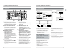
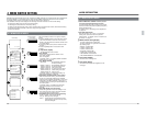
2-5 ON-SCREEN DISPLAY
1. Tape counter display, etc.
Menu switch No. 504 <INFORMATION SELECT>
SUB read-out mode
TC read-out mode
Counter mode
Operation mode
Sub time code
Counter
F
F
F
F
F
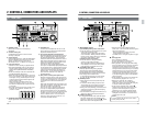
On-screen display
On-screen information is available only via the rear
panel [LINE 2 - SUPER OUT] connector.
1. Tape counter display
● Shows data when the [ON SCREEN] switch on
the sub panel is set to ON.
● You can choose what information is shown with
menu switch No. 504 <INFORMATION
SELECT>.
Only time data is displayed when “TIME (0)” is
selected.
Both time data and VCR operation mode are
displayed when “TIME & MODE (1)” is selected.
● The display position can be shifted horizontally
with menu switch No. 501 <CHARA
H.POSITION> and vertically with No. 502
<CHARA V.POSITION>.
● Set the [ON SCREEN] switch on the sub panel
to OFF to turn off the on-screen display.
* If menu switch No. 513 <EDIT ON SCREEN>
is set to “ON”, you cannot turn the on-screen
display off.
● When menu switch No. 504 <INFORMATION
SELECT> is set to “TIME + SUB TC” or “TIME +
SUB TC + MODE”, sub time code information is
shown simultaneously on a different line.
2. Menu switch setting display
Press the [MENU] button to call up the menu
setting display on screen.
● Select a menu item by turning the jog dial. For
details, refer to “Menu switch setting” on
page 31.
● Pressing the [MENU] button restores the normal
display.
3. Hour meter data display
Hour meter data can be displayed in the Menu
Switch Setting mode. For details, refer to “Hour
meter data display” on page 39.
4. Warning code display
If a malfunction occurs, the corresponding warning
code is automatically displayed.
For details, refer to “Warnings with Indicators” on
page 145.
5. Tape remaining time display
When menu switch No. 505 <REMAIN ENABLE>
is set to “ENABLE(1)”, tape remaining time is
shown in 6 steps.
Player/recorder
indication
2. Menu setting display
0002
DH:DRUM HOUR METER
3. Hour meter data display
4. Warning display 5. Tape remaining time display
WARNING 02 1
CONDENSATION ON DRUM
PLAY
CTL 0:00:00:00
EF
008:CAP LOCK(525)
SW SEL
002:OPERATION LOCK
OFF
003:SYNC SELECT
AUTO
005:AUTO TRACKING
ON
009:CAP RE-LOCKING DIR.
ACCELERATION
* Shown when the tape speed is less than ±0.3x.
Player/recorder indication
When the editing screen display is not shown during swap editing,
this indicates which VCR's data is currently displayed on the tape
counter.
P:When the player is selected (SUBTC is not shown)
R:
When the recorder or both the recorder and player are selected.
Counter mode
CTL : CTL data
TCR : Time code reader data
TC1 : Time code reader data (when the first field is played back)*
TC2 : Time code reader data (when the second field is played
back)*
TCR• : CTL interpolation mode
TCG : Time code generator data
UBR : User bits reader data
UBG : User bits generator data
LTC : LTC data
Drop-frame display (NTSC only)
In recording or playback in the Drop-frame
mode, the counter display is as shown below.
TCR 00:00:00
·
00
Drop frame indication