


44
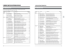
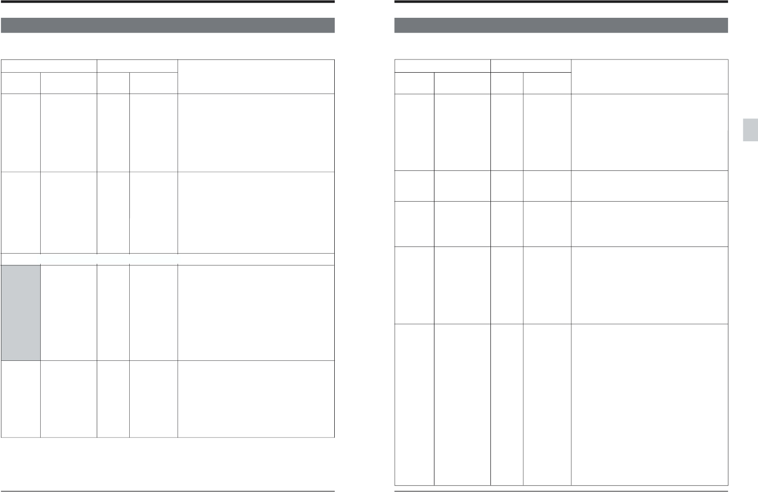
5-2 MENU SWITCH SETTING CONTENT
5 MENU SWITCH SETTING DETAILS
Menu SW On-screen Counter On-screen
No. display display display
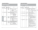
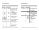
008p CAP LOCK (625) [0] [SW SEL]
12 FIELD
24 FIELD
38 FIELD
009
CAP RE-LOCKING
[0]
[ACCELERATION]
DIR.
1
DECELERATION
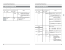
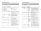
104
CPN LEV./SETUP
0 LOW/ON
(525) [1] [HIGH/ON]
2 LOW/OFF
3 HIGH/OFF
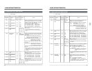
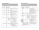
111 VD REC SIGNAL 1 COLOR BAR
SEL.
[2] [BLACK]
4
MULTI BURST
5
PULSE & BAR
[ ] : Factory setting
Selects the video signal output by the internal
signal generator. The selected signal is output in
the EE and Record modes.These signals do not
conform to the SMPTE standard.
COLOR BAR :Color bar is selected. (These are
75% color bar signals).
BLACK :Black signal is selected.
MULTI BURST :Multi Burst signal is selected.
PULSE & BAR :Pulse & Bar signal is selected.
Item
Content
This item should be applied to NTSC signals only.
Sets input/output levels for the [Y, R-Y, B-Y]
connectors on the rear panel.
Sets input/output levels and setup presence.
LOW/ON :Sets component signals to MII levels
with setup.
HIGH/ON :Sets component signals to Bcam levels
with setup.
LOW/OFF :Sets component signals to MII levels
without setup.
HIGH/OFF:Sets component signals to Bcam levels
without setup.
<VIDEO>
Setting
Selects the color frame servo sync system for PAL
signals.
SW SEL: The color frame servo setting is
determined by the sub panel’s [CF]
switch setting.
2 FIELD : The frame servo is set. Color framing is
not executed.
4 FIELD : 4 field color frame servo is executed.
8 FIELD : 8 field color frame servo is executed.
Selects the color frame servo lock direction after
executing the bump function.
If the edit point shifts due to the color frame servo,
select + or - to adjust the edit point.
ACCELERATION:Moves the edit point in the +
direction (locks in the
acceleration direction).
DECELERATION:Moves the edit point in the -
direction (locks in the
deceleration direction).
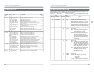
45
Menu SW On-screen Counter On-screen
No. display display display
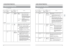
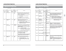
112 ECC MODE [0] [NORMAL]
1
NO CANCEL
2NO
CORRECTION
119 SLOW PICTURE 0 FRAME
[1] [FIELD]
120 NO CTL MUTING 0 OFF
[1] [ON]
124 CHROMA ROTE [0] [CPS]
1 CPN
128 PB EXTENSION 0OFF
LINE [1] [ON]
5-2 MENU SWITCH SETTING CONTENT
5 MENU SWITCH SETTING DETAILS
[ ] : Factory setting
Switches the output chroma phase reference for
component signals or composite signals.
CPS: Varies the phase so that the chroma level is
not changed with the composite vector scope.
CPN: Varies the phase so that the chroma level is
not changed with the component vector
scope.
Set this switch when adjusting the chroma phase
with the video control.
Sets whether or not the video signal extension line
is output during playback.
ON : Outputs the extension line.
When a tape recorded on this unit is played back,
all video signal lines are output.
OFF: Does not output the extension line.
Set to this position when playing back tapes not
recorded on this unit.
*During recording, the following signal lines are
recorded as the EXTENSION LINE.
[525]:LINE 20, 21, 22, 263, 282, 283, 284 and
525 (For LINE 282, the second half only)
[625]:LINE 19, 20, 21, 22, 331, 332, 333, 334 and
623
This menu functions only with tapes recorded on
this unit.
When a tape recorded on this unit is played back
on the BR-D80, BR-D750, BR-D92 or BR-D860,
the EXTENSION LINE is not played back.
For details, refer to page 89.
Item
Content
Setting
Selects the “Field” or “Frame” slow play mode.
FRAME : Outputs a frame picture.
FIELD : Outputs a field picture.
Selects the video signal output when a non-
recorded section (NO CTL) of the tape is played
back.
OFF: Still picture is output.
ON : Black picture is output.
This menu activates or deactivates the error
correction circuit (error correction /error conceal).
NORMAL : Activates all error correction
circuitry.
NO CONCEAL : NO error concealment is applied
NO CORRECTION: Neither the error concealment
nor the error correction circuits
function.
For details, refer to page 80.