


78
CH1
CH2
CH3
CH4/TRACKING
OVER
–60
–40
–30
–20
–10
0
dB
dB
OVER
–60
–40
–30
–20
–10
0
dB
dB
OVER
–60
–40
–30
–20
–10
0
dB
dB
OVER
–60
–40
–30
–20
–10
0
dB
dB
CH1
CH2
CH3
CH4/TRACKING
OVER
–2
–4
+2
+4
0
dB
dB
OVER
–2
–4
+2
+4
0
dB
dB
OVER
–2
–4
+2
+4
0
dB
dB
OVER
–2
–4
+2
+4
0
dB
dB
8 PLAYBACK
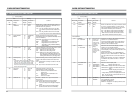
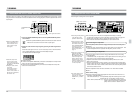
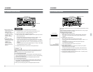
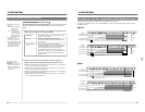
1. Set the [CH4/TRACKING] meter to audio level.
•When the [METER MODE TRACKING] button is illuminated or
blinked, press the [METER MODE TRACKING] button.
[ The [METER MODE TRACKING] button goes out and the
[CH4/TRACKING] meter can be used for the CH4 audio level.
2. Adjust the playback level for each channel (CH1 to CH4) separately with
the [PLAY] volume control.
• To perform fine adjustment, press the [METER MODE FINE] button.
[ The [METER MODE FINE] button is illuminated and the audio
level meter shows a reference fine level of around -20 dBFS or
-18 dBFS.
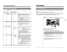
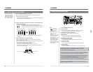
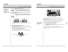
METER MODE
TRACKING
FINE
Normal mode level indication Fine mode level indication
• The reference output level shown by the audio level meter is -20 dBFS or
-18 dBFS.
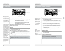
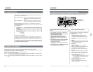
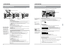
Ⅲ Adjust with the master and balance controls.
The CH1 and CH2 [PLAY] volume controls, and the CH3 and CH4 [PLAY]
volume controls work as one set.
The CH1 and CH3 [PLAY] volume controls serve as master volume control and
the CH2 and CH4 volume controls as balance control.
• Turn the CH1 or CH3 [PLAY] volume control.
The audio on CH2 or CH4 changes along with CH1 or CH3.
• Turn the CH2 or CH4 [PLAY] volume control to adjust the balance between
CH1 and CH2 or CH3 and CH4.
CH1
CH2
CH3
CH4
PLAY
Pair Pair
Master volume control
Balance control
Master volume control
Balance control
8-3. AUDIO PLAYBACK LEVEL ADJUSTMENT
METER MODE
TRACKING
FINE
● The audio level meter’s
reference level
indication changes
depending on the
setting of menu switch
No. 257 <AUD REF.
SIGNAL LEV.> (-20 dB
or -18 dB).
79
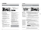
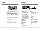
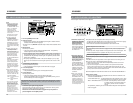
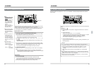
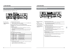
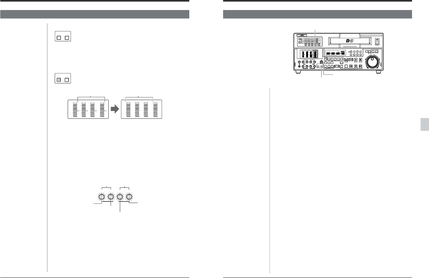
8-4 MANUAL TRACKING AJUSTMENT
8 PLAYBACK
This unit is equipped with an automatic tracking facility which operates during
playback to maintain optimum tracking (with menu switch No. 005 <AUTO
TRACKING> set to “ON (1)”).
With some tapes, noise may still appear — particularly if the tape was recorded on
a different VCR. In this case, manual tracking adjustment is also possible.
1. Set menu switch No. 005 <AUTO TRACKING> to “OFF (0)”.
2. Set the [CH4/TRACKING] meter for tracking.
Press the right [TRACKING METER MODE] button.
[The [METER MODE TRACKING] button blinks when the meter is switched to
Tracking mode.
3. Adjust until the tracking meter level reaches the maximum.
The Auto Tracking mode can be restored by setting menu switch No. 005 <AUTO
TRACKING> to “ON (1)”.
POWER
ON
I
OFF
O
M
H
F
S
REC
MENU
PLAY
PAUSE/ STILL
REW
STOP
FF
EJECT
PHONES
CH1
CH2
CH3
CH4
REC
PLAY
PULL FOR VARIABLE
TRACKING
CH1
CH1
CH2
CH3
CH4/
TRACKING
SET
HOLD
PB
PB/EE
COUNTER
UB
CONDITION
AUDIO
INPUT
VIDEO
INPUT
AUDIO
MONITOR
PULL
RELEASE
RESET
VCON
REMOTE
TOP VIDEO AUDIO
OTHERSON SCREENTIME CODESERVO/SYS
USER
INSERT
STAND BY
PLAYER
SEARCH
VAR
P.PLAY
DA3
DA2
DA1VIDEO
ASSEM
IN
ENTRY
OUT
CANCEL
SHIFT
REVIEW
METER MODE
TRACKING
FINE
PREVIEW
AUTO EDIT
PREROLL
TC
RECORDER
DA4
VIDEO CASSETTE RECORDER
BR-D95U
STILL
X-1
REV
FWD
X1
CH2
CH3
CH4
CH1
CH2
CH3
CH4
CH1
CH2
CH3
CH4
SIF
SDI
AES/EBU
AUDIO INPUT / AUDIO MONITOR SELECT
LINE
CPN
L
ANALOG
R
PULL
RELEASE
CTL
P.READ
AUTO
OFF
V.VAR
REMOTE
PB/EE
16:9
TC
UB
DF
SERVO
GENCF
AP
525
OVER
–60
–2
–4
+2
+4
0
–40
–30
–20
–10
0
dB
dB
R P
OVER
–60
–2
–4
+2
+4
0
–40
–30
–20
–10
0
dB
dB
R
P
OVER
–60
–2
–4
+2
+4
0
–40
–30
–20
–10
0
dB
dB
R
P
OVER
–60
–2
–4
+2
+4
0
–40
–30
–20
–10
0
dB
dB
R
P
625
Variable Motion
COMPONENT DIGITAL
[METER MODE TRACKING] button
[TRACKING] adjust knob
[CH4/TRACKING] meter
● In the Auto Tracking
mode, the [METER
MODE TRACKING]
button lights.