


104
11 EDITING
11-1 OUTLINE
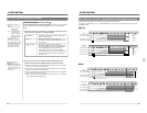
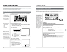
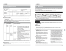
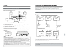
Two electronic editing modes are available: insert editing and assemble editing. Signals from a video camera, on-
air signals and playback signals from another VCR can be used in either type of editing.
CTL signals required
Edit-out point
Edit-in pointPreroll point
Recorder
* Since the full erase head operates during assemble
editing, a non-recorded segment is produced after the
postroll point. If assemble editing is applied in the
middle of a recorded tape, the picture will be distorted
after the postroll point.
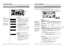
Insert editing
Insert editing allows you to insert new audio or video
material between existing scenes that have already
been recorded. You can choose different video and
audio and combine them for insertion.
CTL signals must be recorded continuously in the
section where the new material is being inserted.
Before editing, record CTL signals for a period
exceeding the editing time.
Edit-out point
Edit-in pointPreroll point
CTL signals required
Recorder
● To record CTL signals, record a black picture from the built-in signal generator or connect a camera or a
standard TV signal generator and record the output signals.
● Editing is not possible from the very beginning of the tape. The first edit-in point must be registered after the
preroll section.
● Audio signals are not output when color bar signal from the built-in signal generator are inserted for editing
(including preview). Do not select the audio channel for insertion of the color bar signal from the built-in
signal generator. It may not be possible to insert the signal properly on the audio channel.
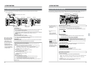
Assemble editing
With assemble editing, scenes are added one after
the other in predetermined order. Video, audio, and
control signals are recorded simultaneously. To
ensure stable editing, CTL signals must be recorded
prior to the first edit point for a period exceeding the
preroll time (typically, about 30 seconds).
● Preroll time
It takes a few seconds for the tape to stabilize after
tape running is started. To ensure that the tape is
stable before it reaches the edit point, the tape
must start running a few seconds before the edit-in
point (prerolling).
Select the preroll time from 0 to 15 seconds with
the recorder’s menu switch No. 320 <PREROLL
TIME>. Use the remote control setting only when
executing editing via a remote controller.
● CTL counter values based on the TIMER-1
PRESET command (44.00) from the editing
controller can be preset only in the Non-drop Frame
mode (NTSC).
● Program Playback speed can be varied between
90% and 110%. The range is always the same
even if an external controller or other unit is
connected that sets the range outside this limit.
Cautions
● The displayed image may be distorted when the
editing mode is preset from an editing controller
during editing or the mode is switched between
EE and PB. This is normal. It is not a
malfunction. The distortions appear in the
editing output image but are not recorded.
● The V. Fade function may not function correctly
when a tape with edited audio is played back.
This is normal. It is not a malfunction.
● Noise may be recorded if all insert modes are
canceled during editing with any of editing mode
select buttons. This is normal. It is not a
malfunction.
● Noise may be heard when editing is on or off in
the Playback mode. This is normal. It is not a
malfunction.
105
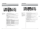
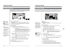
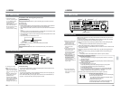
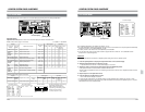
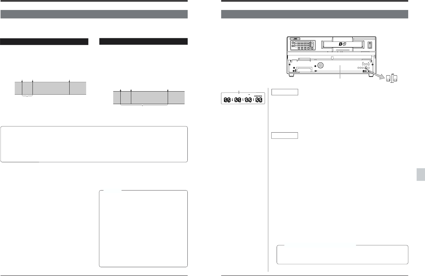
11-2 COLOR FRAME SERVO SETTING
NTSC : 4-field color frame servo function available
PAL : 4 or 8-field color frame servo function available
POWER
ON
I
OFF
O
CH1
AUDIO
INPUT
VIDEO
INPUT
AUDIO
MONITOR
VIDEO CASSETTE RECORDER
BR-D95U
CH2
CH3
CH4
CH1
CH2
CH3
CH4
CH1
CH2
CH3
CH4
SIF
SDI
AES/EBU
AUDIO INPUT / AUDIO MONITOR SELECT
LINE
CPN
L
ANALOG
R
SERVICE USE ONLY
8
OFF
4
ON
Variable Motion
COMPONENT DIGITAL
OFF
RF
HID GND
8
ON
ON
4
OFF
TIME CDOE
INT
FREE
PRESET
EXT
DF
NDF
REC
REGEN
ON SCREENCF
(625)
CF
(625)
ⅢColor frame-related menu
switches
• No. 009 <CAP RE-
LOCKING DIR.>
Selects the direction of
the color frame servo
lock.
• No. 387 <CF FLAG
REPLY>
Selects the field unit for
the color frame flag
transmitted from the 9-pin
remote control connector.
(See page 106.)
• No. 421 <TCG CF FLAG>
Turns the color frame flag
for the time code bit ON/
OFF. (See page 106)
ⅢColor frame editing is still
possible even when
material that does not
contain color frame
information (have no 4-field
NTSC color frame
information or 8-field PAL
color frame information) is
inserted in a color frame-
recorded section. Once the
new material has been
inserted, color frame
editing can be performed
by re-editing. In this case,
the [CF] indicator on the
main unit lights.
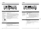
11 EDITING
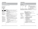
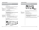
Front sub panel
M
H
F
S
CONDITION
CF
525
[CF] indicator
Recording
●Color frame information is always recorded regardless of the setting of the front
sub panel’s CF switches and menu switches (except during editing).
NTSC:4-field color frame
PAL :8-field color frame
●During recording, the CF indicator lights on the counter display.
●If you want to synchronize time code with color frame, set menu switch No. 421
<TCG CF FLAG> to “ON” or “AUTO”.
Playback
The color frame servo function can be set with the front sub panel’s CF switches
and menu switches.
Ⅲ Front sub panel switch setting
•Set menu switch No. 008 <CAP LOCK (525)> or No. 008p <CAP LOCK (625)>
to “SW SEL”.
•Set the [CF] switch on the front sub panel to “ON”.
For PAL, select the 4 or 8-field color frame servo with the [4/8] switch.
When the [CF] switch is set to “OFF”, the frame servo is activated.
Ⅲ Menu switch setting
•For NTSC, set menu switch No. 008 <CAP LOCK (525)> to “4FIELD”.
•For PAL, set menu switch No. 008p <CAP LOCK (625)> to “4FIELD” or
“8FIELD”.
Menu switch No. 008 <CAP LOCK>
SW SEL:Select with the front sub panel’s [CF] switches.
2FIELD :Playback is performed with the 2-field servo system. Color framing is
not executed.
4FIELD :Playback is performed with the 4-field color frame servo system.
8FIELD :Playback is performed with the 8-field color frame servo system (PAL
only).
●[CF] indicator
If the front sub panel [CF] switches are set to any position except OFF, the CF
indicator lights whenever a tape with color frame information is played back.
Editing precision during color frame editing
When the color frame servo function is used, the edit point may shift to
maintain color frame continuity even though menu switch No. 393 <SYNC
GRADE> is set to “ACCURATE”.