


6
MAIN FEATURES
● Do not record important material in the first two or
three minutes of a tape.
● It may be unlawful to use any material recorded
from TV broadcast programs or pre-recorded
programs without the consent of the owner of
copyright, except in cases where this material is
recorded exclusively for personal use.
● JVC is not liable for compensation for loss or
damage to recordings in the event this unit fails to
record or play back properly because the unit
malfunctions or a defective video cassette tape is
used.
● This unit is designed for professional use.
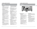
CAUTION: 4-channel audio
insert editing
Do not try to perform audio insert
editing on tapes with 4 audio channels
when using a 2-channel audio DIGITAL
S VCR (BR-D85U/E, BR-D80U/E, BR-
D750U/E).
If audio insert editing is executed,
audio signals recorded on DA3 and
DA4 will be erased.
Thank you for purchasing the BR-D95U DIGITAL S
Video Cassette Recorder with electronic editing
capabilities.
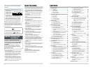
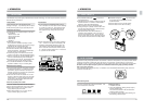
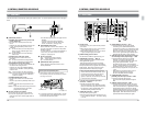
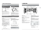
●This unit can be used with either NTSC or PAL
signal systems. Before using this unit, first select
the signal system.
The signal system
you select will be
indicated on the
counter display
with “525” for NTSC
and “625” for PAL. For instructions on how to
select the signal system, refer to “4-2 VIDEO
SIGNAL SYSTEM SELECTION” on page 30.
●The optional SA-D95U digital interface board is
required for input/output of serial digital signals.
CONDITION
525
625
Signal system indication
Counter display
● Superb picture quality achieved by the DIGITAL S
format using 4:2:2 component digital processing
● Independently editable 4-channel PCM high-quality
sound
4-channel PCM high-quality sound with 16-bit 48
kHz sampling. 4-channel audio can be edited
independently.
● High-density metal tape based on the W-VHS
format
● Built-in time code generator/reader to enable
recording and reading of SMPTE/EBU-Standard
time code and user bits
● Pre-read function
This function makes it possible to execute A/B roll
editing using only one player (video/audio insert
only).
● Swap editing
The swap control function allows the player VCR to
be controlled from the recorder VCR via 9-pin
remote cable. This allows automatic editing even
when an editing controller is not available.
● Audio split editing
Audio edit start points can be set separately with
the video signal edit start point as a reference.
● Color frame servo function
This function ensures that continuity of the color
subcarrier phase is maintained during editing.
● Audio V fade function
This function fades the audio level during a
transition in V shape to reduce noise.
● Complete analog interface with input/output
terminals for composite, color difference component
and analog audio signals included as standard
● Internally installable serial digital interface board
optionally available for configuration of fully digital
systems
● Jog/search dial
● Built-in noiseless slow playback facility for noiseless
playback within a speed range of approximately
–1 to +1 normal
● Audio monitor facility for search
The D-9 format provides two linear audio channels,
enabling audio monitoring even during video shuttle
search.
● Tiltable front panel
● Playback audio output adjustment function
● Recording audio input adjustment function
● Video output adjustment function
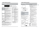
Whenever (NTSC) or (525) is specified in this
manual, the accompanying information applies only
to the NTSC signal system. Similarly, information
that is specified as (PAL) or (625) applies only to the
PAL signal system.
This video cassette recorder uses the DIGITAL
S format. It can only be used with video tape
cassettes bearing the “
” or “
COMPONENT DIGITAL
” logo.
COMPONENT DIGITAL
7
CONTENTS
1INTRODUCTION ............................................... 8
1-1 Outline .................................................... 8
1-2 Maintenance ........................................... 9
1-3 Precautions.............................................10
1-4 Video Cassette .......................................11
1-5 Head Cleaning........................................11
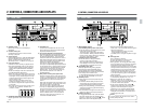
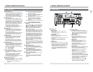
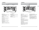
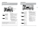
2 CONTROLS, CONNECTORS AND DISPLAYS 12
2-1 Front Panel .............................................12
2-2 Sub Panel ...............................................18
2-3 Rear Panel..............................................19
2-4 Counter Display ......................................21
2-5 On-screen Display ..................................23
3 CONNECTIONS ................................................25
3-1 Input Connections...................................25
3-2 Output Connections................................26
3-3 Control System Connections ..................27
4 MENU SWITCH SETTING.................................28
4-1 Menu Display Modes ..............................28
4-2 Video Signal System Selection...............30
4-3 Menu Switch Setting...............................31
4-4 Saving and Calling Up Menu Switch
Settings...................................................32
4-5 Calling Up Functional Menu Switch (Direct
Access Function) ....................................33
4-6 User Page Registration/Change/Delete
(User Page Function) ..............................34
4-7 How to Lock the Menu Switch Settings.....37
4-8 Recording Current Adjustment ...............38
4-9 Hour Meter Data Display ........................39
5 MENU SWITCH SETTING DETAILS ................40
5-1 Menu Switch List.....................................40
5-2 Menu Switch Setting Content .................43
6 PREPARATION.................................................65
6-1 Operation Mode Lock .............................65
6-2 Standby ON/OFF....................................66
6-3 Loading and Unloading the Cassette......67
7 RECORDING .....................................................68
7-1 Preparation for Recording.......................68
7-2 Input Video and Audio Signal Selection..69
7-3 Audio Monitor Output Signal Selection...70
7-4 Audio Record level Adjustment...............71
7-5 Basic Recording Operations...................73
7-6 Digital audio signal input/output..............74
8 PLAYBACK .......................................................75
8-1 Preparation for Playback ........................75
8-2 Basic Playback Operations.....................76
8-3 Audio Playback Level Adjustment ..........77
8-4 Manual Tracking Adjustment ..................79
8-5 Error Correction ......................................80
8-6 Audio V.Fade Function ...........................80
8-7 Simplified Playback Speed
Adjustment Function ...............................81
8-8 Shuttle Search/Jog Operation.................82
8-9 Variable Slow Playback ..........................83
8-10 Program Playback ..................................85
8-11 FF, REW and Counter Memory
Functions ................................................86
8-12 Repeat Playback.....................................86
9 OTHER FUNCTIONS ........................................87
9-1 Extra Line Data Recording/Playback......87
9-2 EXTRA LINE, VITC LINE, V. BLANK
MASK and PB EXTENSION LINE
settings ...................................................89
9-3 Simultaneous Operation .........................90
9-4 Fixed Time Cue Up Function..................91
9-5 Multi Cue-Up Function............................92
9-6 Striping Rec Function .............................94
10 HOW TO USE TIME CODE ...............................96
10-1 Time Code Display .................................96
10-2 Time Code Initial Setting (Preset)...........97
10-3 Time Code Recording ..............................99
10-4 Time Code Playback.............................101
10-5 Sub Time Code Recording and
Playback ...............................................102
10-6 Time Code Switch Setting for Editing ...103
11 EDITING...........................................................104
11-1 Outline ..................................................104
11-2 Color Frame Servo Setting ...................105
11-3 Swap Editing.........................................107
11-4 Audio Split Editing.................................112
11-5 Other Function ......................................113
11-6 Manual Editing ......................................114
11-7 Editing with the Pre-read Function........115
12 EDITING SYSTEM PHASE ADJUSTMENT....117
12-1 Connection............................................117
12-2 Adjustment............................................118
12-3 Dubbing Loop Function.......................... 122
13 RS-232C Protcol .............................................123
13-1 Command tables...................................123
13-2 RS-232C commands ............................124
13-3 Speed/data correspondence table........134
13-4 Contents of the sense commands ........135
13-5 Menu switch setting information ...........137
14 TROUBLESHOOTING ....................................145
14-1 Warnings with Indicators.......................145
14-2 Troubles not to be Warned by
Indicators ..............................................147
15 APPENDIX.......................................................148
15-1 Operation button combinations.............148
15-2 Optional Accessories ............................148
15-3 Index .....................................................149
16 SPECIFICATIONS ...........................................150