


124
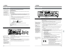
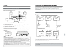
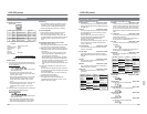
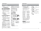
Ⅲ RS-232C specifications
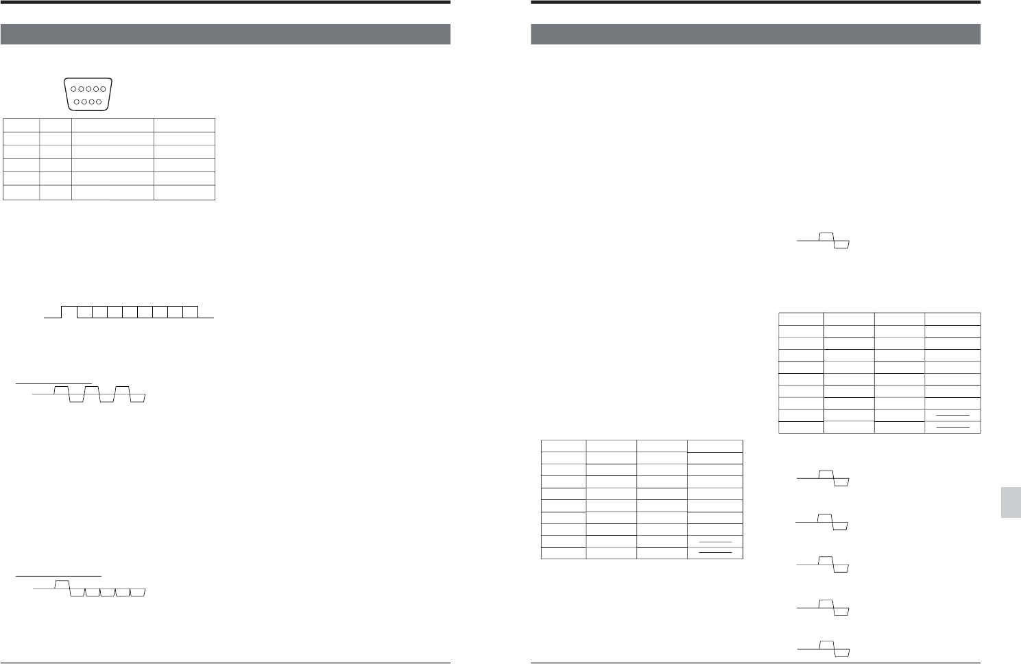
9PIN D-SUB
PIN No. Signal Operation Direction
2 RxD Reception data VCR p CPU
3 TxD Transmission data VCR [ CPU
4 DTR Data terminal ready VCR [ CPU
5 GND Signal ground
6 DSR Data set ready VCR p CPU
Note: CPU means a controller such as a personal
computer.
Mode : Non-synchronized
Character length :8 bits
Parity check : None
Start bit : 1
Stop bit : 1
Data rate : 9600 bps
Bit construction
15
69
D0 D1 D2 D3 D4 D5 D6 D7
p
p
Start bit Stop bit
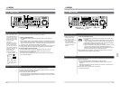
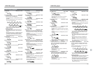
Ⅲ Basic format
(1) The VCR returns [0A: ACK]·[0B: NAK]·[02:Error]
in response to each byte sent from the controller.
Eg.: E5: EditPreset
CPU: Controller such as a personal computer
VCR: BR-D95 series
• In response to the first byte sent from the
controller, the VCR returns either [ACK], [NAK]
or [Error] within 100 µs.
• The controller confirms the reply from the VCR
and then outputs the second byte. The VCR
returns either [ACK], [NAK] or [Error] within
100 µs.
• The controller confirms the reply from the VCR
and then outputs the third byte. The VCR
returns either [ACK], [NAK] or [Error] within
100 µs.
(2) When the data is recognized by the controller, the
VCR returns the standard byte data.
Eg.: D7: StatusSense
CPU: Controller such as a personal computer
VCR: BR-D95 series
• The VCR starts to output data within 100 µs
after receiving the first byte from the controller.
Stop bits are inserted between output data.
CPU E5 3* 3*
VTR 0A 0A 0A
CPU D7
VTR ** ** ** ** **
Ⅲ Receiving
• The VCR always receives commands from the
controller. The VCR also replies to all “sense”
commands such as StatusSense/TimeSense.
• Switch Remote/Local on this unit to “Remote”.
Ⅲ Time management
Command output timing is managed as follows:
• The minimum command interval is 10 ms.
• The minimum byte interval is 100 µs when the
controller outputs the next byte without confirming
the [ACK], [NAK] or [Error] returned from the
VCR.
Ⅲ Processing method when an error occurs
(1) When NAK (0B) is returned
The first byte command that the VCR was unable
to receive is sent. Output another command.
(2) When Error (02) is returned <The Error section of
StatusSense (bit-0 of the first byte) describes the
Error mode.>
•The VCR receives an illegal command for the
second byte and later. With ClearError [41],
the previous byte is canceled.
•When ClearError [41] is transmitted repeatedly
because Error [02] is returned more than once,
ACK [0A] is returned to release the Error mode.
The Error mode can also be released by
canceling the commands being input with Clear
[56].
(3) If ACK [0A], NAK [0B], Error [02] or Data is not
returned
The VCR does not recognize the byte. Cancel the
commands being input with Clear [56] and transmit
the command again.
(The VCR replies within 1 ms after receiving the
command from the controller.)
(4) When NotTarget [05] is returned
The target point on the tape specified with
CueUpWith Data/Preroll does not exist. Input a
different value and try again.
13 RS-232C protocol
13-2 RS-232C Commands
125
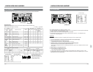
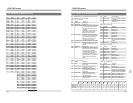
Ⅲ Return command from the VCR
01: Completion Basic/JVC-1 Table
The VCR outputs this command after completing
the requested operation (CueUp With Data/Preroll/
AutoEdit, etc.).
02: Error Basic/JVC-1 Table
The VCR outputs this command when invalid data
is received.Bit-0 (Error) of the first byte is set for
[D7: StatusSense].
In this condition, the VCR will not accept any
command except the StatusSense command.
The Error mode can be released with [41:
ClearError] or [56: Clear].
To cancel the entire command, use [56: Clear]. To
cancel only the most recently transmitted data,
use [41: ClearError].
03: Cassette Out Basic/JVC-1 Table
The VCR outputs this command when the eject
operation is complete.
05: Not Target Basic/JVC-1 Table
The VCR outputs this command when CueUp
With Data/Preroll operation cannot be completed
normally.
0A: ACK Basic/JVC-1 Table
This command is returned when the defined
command is received.
0B: NAK Basic/JVC-1 Table
This command is returned when an undefined or
invalid command is received.
ASCII code Basic/JVC-1 Table
Alphanumeric equivalents for certain “Sense”
commands.
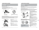
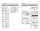
Ⅲ Auxiliary commands to the VCR
40: Enter Basic/JVC-1 Table
If this command is transmitted during data trans-
mission, data transmitted after this command will
be zero (=30) or space (=20). More information
on how to use this command can be found in the
descriptions of related commands where its use is
valid.
41: Clear Error Basic/JVC-1 Table
In the Error mode, this command cancels the last
numeric/data command.
The Error mode is engaged when bit-0 (Error) of
the first byte in D7: StatusSense is “1”.
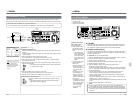
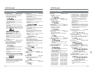
56: Clear Basic/JVC-1 Table
In the Error mode, this command releases the
command.
The Error mode is engaged when bit-0 (Error) of
the first byte in D7: StatusSense is “1”.
ASCII code Basic/JVC-1 Table
Alphanumeric equivalents for certain Preset
commands.
TxD 56
RxD 0A
13-2 RS-232C Commands
13 RS-232C protocol
61: a
62: b
63: c
64: d
65: e
66: f
67: g
68: h
69: i
6A: j
6B: k
6C: l
6D: m
6E: n
6F: o
70: p
71: q
72: r
73: s
74: t
75: u
76: v
77: w
78: x
79: y
7A: z
20: Space
2D: -
30: Zero
31: 1
32: 2
33: 3
34: 4
35: 5
36: 6
37: 7
38: 8
39: 9
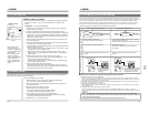
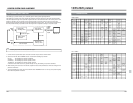
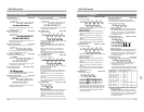
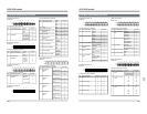
TxD 3A
RxD 0A
TxD 3B
RxD 0A
TxD 3C
RxD 0A
TxD 3D
RxD 0A
TxD 3E
RxD 0A
Ⅲ Corresponding commands
3A: Play key Basic/JVC-1 Table
Playback
3B: Fwd-4 Key Basic Table
4x playback in the forward direction
3C: Fwd-0.09 Key Basic Table
0.09x playback in the forward direction
3D: Fwd Still Key Basic Table
Still playback
3E: Fwd-6 Key Basic Table
6x playback in the forward direction
61: a
62: b
63: c
64: d
65: e
66: f
67: g
68: h
69: i
6A: j
6B: k
6C: l
6D: m
6E: n
6F: o
70: p
71: q
72: r
73: s
74: t
75: u
76: v
77: w
78: x
79: y
7A: z
20: Space
2D: -
30: Zero
31: 1
32: 2
33: 3
34: 4
35: 5
36: 6
37: 7
38: 8
39: 9