


14
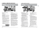
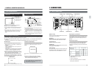
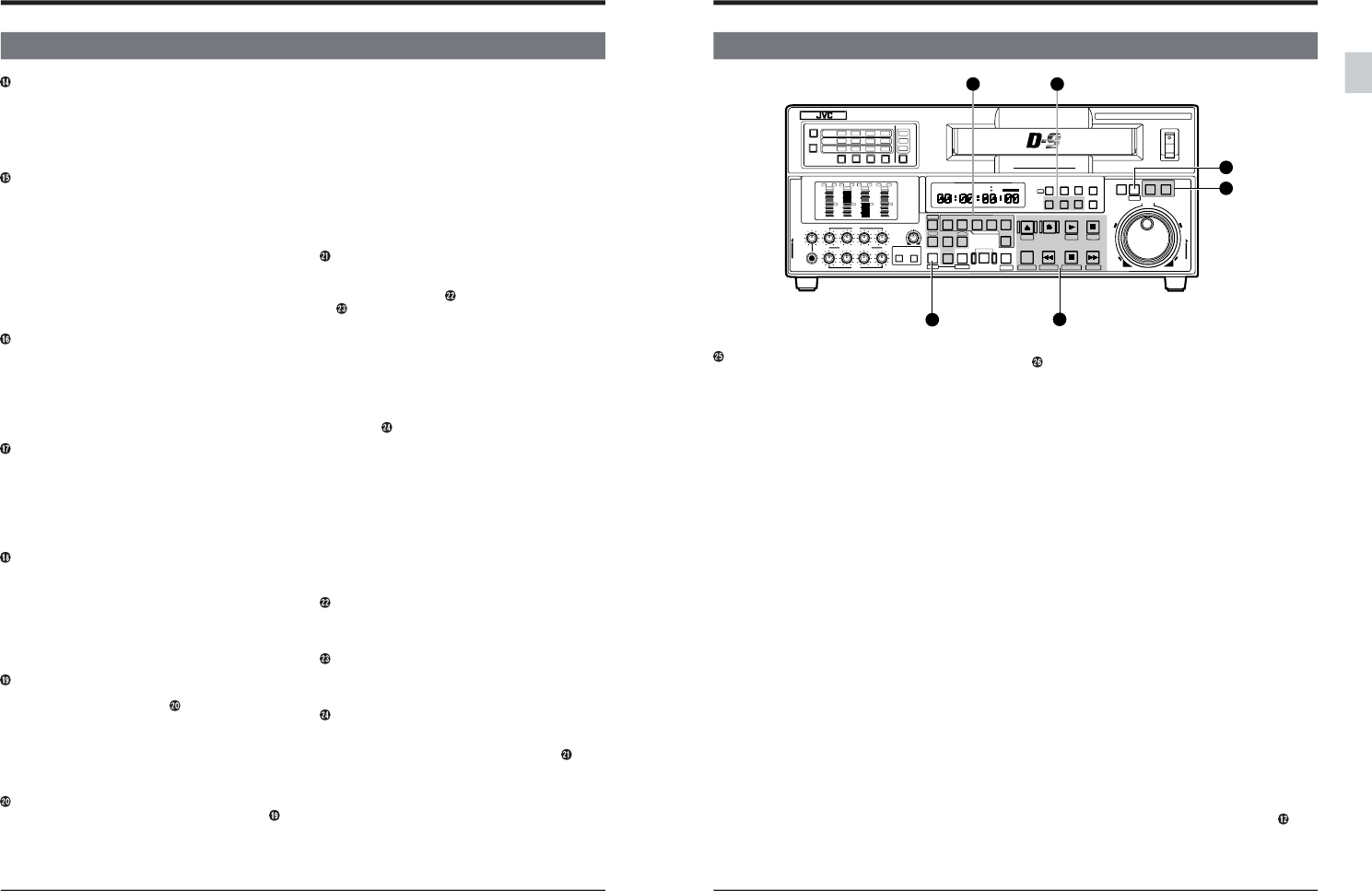
2-1 FRONT PANEL
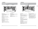
2 CONTROLS, CONNECTORS AND DISPLAYS
LINE: Lights when composite video signal input
(via rear panel's [COMPOSITE LINE IN]
connector) is selected.
CPN: Lights when component video signal input
(via rear panel's [COMPONENT IN]
connector) is selected.
All lit: All indicators light when the signal from the
internal signal generator is selected.
The type of signal can be selected with
menu switch No. 111 “REC SIGNAL
SELECT”.
Blinking: The indicator blinks if no signal is input or
if the wrong type of signal is input.
[AUDIO INPUT/AUDIO MONITOR SELECT]
indicators
Show whether the input or monitor audio signal is
selected. Press the [AUDIO INPUT] button or
[AUDIO MONITOR] button to switch between
the input or monitor indication.The channel
indicator blinks if the selected signal does not
conform to the standard.
Along with the input indication, the type of signal
(SDI, AES/EBU or ANALOG) is shown. With the
monitor indication, the audio channel (CH1, CH2,
CH3, or CH4) output to the monitor output L or R
channel is shown.The channels can be switched
with the audio signal select buttons. When
these three indicators (SDI, AES/EBU, ANALOG)
are lit simultaneously, audio signals (1 kHz sine
wave) from the built-in signal generator are
selected. The signals from the built-in signal
generator can be either 1 kHz audio signals or no
sound. This is selectable with menu switches
(No. 253 to No. 256).
When the input audio signal indication is selected,
these indicators blink if no SDI or AES/EBU signal
is input. SDI and AES/EBU can only be selected
when the optional SA-D95U digital interface board
is installed.
[AUDIO INPUT] button
Press to select the input audio signal for the
[AUDIO INPUT/AUDIO MONITOR SELECT]
indicators. The button illuminates when selected.
[AUDIO MONITOR] button
Press to select the monitor audio signal for the
[AUDIO INPUT/AUDIO MONITOR SELECT]
indicators. The button illuminates when selected.
Audio signal select buttons
Press to select the input audio signal or monitor
audio signal.
The selected audio signal is shown by the
[AUDIO INPUT/AUDIO MONITOR SELECT]
indicators.
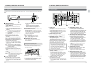
[PB PB/EE] button
Press to select the playback (PB) exclusive mode
or PB/EE auto switching mode. The selected mode
is shown by the indicators in the upper section of
the counter display. When the PB/EE Auto
Switching mode is engaged, set the VCR to the EE
mode with menu switch No. 314 <PB/EE MODE>.
[REMOTE] button
Press to select remote/local operation. When
remote operation is selected, “REMOTE” is shown
in the upper section of the counter display. In the
“REMOTE” mode, the unit can be operated via the
remote controller connected to the rear panel’s
[REMOTE IN (9P)] or [RS-232C] connector. On
the VCR itself, only the [STAND BY], [STOP] and
[EJECT] buttons will remain operable.
To operate the VCR locally, that is with its
operation buttons, press the [REMOTE] button so
that the “REMOTE” indicator goes out.
[VCON] button
Press to adjust the video/audio parameters.
Adjustable items are shown on the counter display.
Turn the jog dial while pressing the [SEARCH]
button to make adjustments.
You can adjust the video parameters by connecting
an optional video controller to the rear panel’s
[VIDEO CONTROL] connector. (See page 118.)
[RESET] button
Press to reset the CTL counter to “0:00:00:00”.
The time code and user bits cannot be reset.
When the edit points have been set, these
settings are canceled.
When setting the fixed time cue up, press this
button to reset the counter to “00:00:00:00”. For
details, refer to “Fixed Time Setting” on page 91.
[COUNTER] button
Press to switch the counter between CTL counter,
time code, or user bits display. Press this button while
pressing the [SHIFT] button to display user bits.The
selected counter display mode is shown by the
indicators in the upper section of the counter display.
CTL: CTL counter display
TC: Time code display
UB: User bits display
Input video signal button
Press to select input video signals. The selected
video signal is shown by the [VIDEO INPUT]
indicators.
SIF can only be selected when the optional
SA-D95U digital interface board is installed.
A menu switch is provided to prevent
misoperation. Refer to the menu switch setting for
No. 371 “INPUT SELECT SAFETY”.
[VIDEO INPUT] indicators
Show the type of video signal selected with the
input video signal switch.
SIF: Lights when serial video signal input (via rear
panel's [SERIAL V/A IN] connector) is
selected.
15
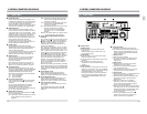
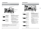
2-1 FRONT PANEL
2 CONTROLS, CONNECTORS AND DISPLAYS
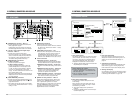
Setting buttons
Ⅲ [MENU] button
● Press this button to enter the Menu Switch
Setting mode.
Press this button again to switch back to the
Counter Display mode.
Ⅲ [SET] button
● Press this button to store menu switch setting
data in the VCR’s memory.
● Press this button to preset data in the time code
generator.
● Use this button to end video parameter
adjustment or to use the counter memory
function.
Ⅲ [HOLD] button
● Press this button to preset data in the time code
generator. To preset time code, the [COUNTER]
switch must be set at “TC”. To preset user bits, the
[COUNTER] switch must be set at “UB”.
* This button is effective only when the [INT/EXT]
switch on the time code setting section is set to
“INT” and the [PRESET/REGEN] switch is set
to “PRESET”.
Operation buttons
● All buttons are illuminated when pressed.
● The labels printed under the operation buttons
indicate the menu items displayed when the
button is pressed in the Menu Switch Setting
(Direct Access) mode.
Ⅲ [EJECT] button
● Press to eject the cassette.
● TOP menu switch items are displayed when
this button is pressed in the Menu Switch
Setting mode.
Ⅲ [REC] button
● Engages the Record mode when pressed
together with the [PLAY] button.
● To monitor the EE picture during playback,
press and hold this button.
● Press this button in the Stop mode to check
preset data in the time code generator.
Ⅲ [PLAY] button
● Press to start playback. If pressed together with
the [REC] button, recording will start.
● Video menu switch items are displayed when
this button is pressed in the Menu Switch
Setting mode.
● When menu switch No. 301 <DIRECT
SEARCH> is set to “OFF”, hold this button
down and turn the search dial during play to
perform variable slow playback.
● By turning the jog dial while pressing this button
in the Play mode, you can vary playback speed
between 0 (Still) and +2 (double-speed) Refer
to “Simplified playback speed adjustment
function” on page 84.
● In the Program Playback mode, hold the
[VAR/P.PLAY] button down and press this
button to execute program playback.
POWER
ON
I
OFF
O
M
H
F
S
REC
MENU
PLAY
PAUSE /STILL
REW
STOP
FF
EJECT
PHONES
CH1
CH2
CH3
CH4
REC
PLAY
PULL FOR VARIABLE
TRACKING
CH1
CH1
CH2
CH3
CH4/
TRACKING
SET
HOLD
PB
PB/EE
COUNTER
UB
CONDITION
AUDIO
INPUT
VIDEO
INPUT
AUDIO
MONITOR
PULL
RELEASE
RESET
VCON
REMOTE
TOP VIDEO AUDIO
OTHERSON SCREENTIME CODESERVO/SYS
USER
INSERT
STAND BY
PLAYER
SEARCH
VAR
P.PLAY
DA3
DA2
DA1VIDEO
ASSEM
IN
ENTRY
OUT
CANCEL
SHIFT
REVIEW
METER MODE
TRACKING
FINE
PREVIEW
AUTO EDIT
PREROLL
TC
RECORDER
DA4
VIDEO CASSETTE RECORDER
BR-D95U
STILL
X-1
REV
FWD
X1
CH2
CH3
CH4
CH1
CH2
CH3
CH4
CH1
CH2
CH3
CH4
SIF
SDI
AES/EBU
AUDIO INPUT / AUDIO MONITOR SELECT
LINE
CPN
L
ANALOG
R
PULL
RELEASE
CTL
P.READ
AUTO
OFF
V.VAR
REMOTE
PB/EE
16:9
TC
UB
DF
SERVO
GENCF
AP
525
OVER
–60
–2
–4
+2
+4
0
–40
–30
–20
–10
0
dB
dB
R
P
OVER
–60
–2
–4
+2
+4
0
–40
–30
–20
–10
0
dB
dB
R P
OVER
–60
–2
–4
+2
+4
0
–40
–30
–20
–10
0
dB
dB
R
P
OVER
–60
–2
–4
+2
+4
0
–40
–30
–20
–10
0
dB
dB
R
P
625
Variable Motion
COMPONENT DIGITAL
28
25
27
12
26
29