


136
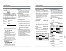
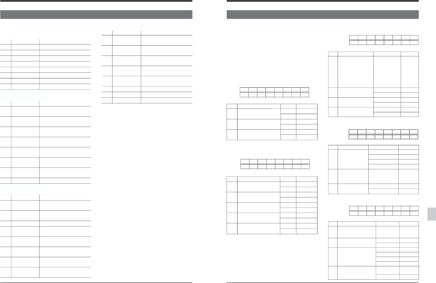
13-4 Contents of the sense commands
13 RS-232C protocol
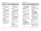
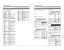
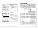
JVC Status (No. 4) Forth byte
Bit Status Remarks
Bit-7 TBC board The TBC board is installed.
Always “1”
Bit-6 TC board The TC board is installed.
Always “1”
Bit-5 DA3 Ins Lamp Audio-3 Insert editing mode
is selected.
Bit-4 DA4 Ins Lamp Audio-4 Insert editing mode
is selected.
Bit-3 Auto mode Auto Edit/Preview/Review
being executed.
Bit-2 Unused Always “0”
Bit-1 Unused Always “0”
Bit-0 Unused Always “0”
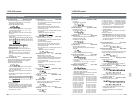
The bit assignment for status data each byte returned
with DD: JVC Status Sense is as follows:
JVC Status (No. 1) First byte
Bit Status Remarks
Bit-7 Undefined Always “1”
Bit-6 Undefined Always “0”
Bit-5 Unused Always “0”
Bit-4 Unused Always “0”
Bit-3 Unused Always “0”
Bit-2 Unused Always “0”
Bit-1 JVC Table 1 JVC Table-1 is selected.
Bit-0 Local “Local” is selected.
JVC Status (No. 2) Second byte
Bit Status Remarks
Bit-7 Generator The TC generator is selected
for the current timer mode.
Bit-6 UB UB is selected for the current
timer mode.
Bit-5 TC TC is selected for the current
timer mode.
Bit-4 CTL CTL is selected for the
current timer mode.
Bit-3 CTL CTL
Interpolation Interpolation
Bit-2 DF DF is selected for the current
timer mode.
Bit-1 LTC LTC is selected for the
current timer mode.
Bit-0 Unused Always “0”
JVC Status (No. 3) Third byte
Bit Status Remarks
Bit-7 REC Run TC setting is 1: REC Run 0:
Free Run.
Bit-6 Regen TC setting is 1: Regen 0:
Preset.
Bit-5 Ext TC setting is 1: Ext 0: Int
Bit-4 TC Ins Lamp TC Insert editing mode is
selected.
Bit-3 DA1 Ins Lamp Audio-1 Insert editing mode
is selected.
Bit-2 DA2 Ins Lamp Audio-2 Insert editing mode
is selected.
Bit-1 V Ins Lamp Video Insert editing mode is
selected.
Bit-0 Assem Lamp Assemble editing mode is
selected.
137
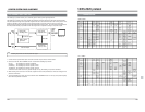
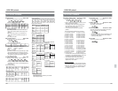
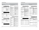
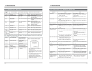
13-5 Menu switch setting information
13 RS-232C protocol
The set value expresses the corresponding bit value.
2 bits or more are expressed as follows:
00
11
210
311
4 100
5 101
::
SERVO information/SYSTEM information-1
DATA0 01
Corresponding menu switches
No. Menu switch name Setting Set value
002 OPERATION LOCK OFF 0
ON 1
003 SYNC SELECT EXT 1
AUTO 3
005 AUTO TRACKING OFF 0
ON 1
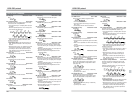
SYSTEM information-2
DATA0 08
Corresponding menu switches
No. Menu switch name Setting Set value
D95 525/625 525 0
625 1
300 DIRECT EJECT OFF 0
ON 1
301 DIRECT SEARCH OFF 0
ON 1
302 BACK SPACE OFF 0
ON 1
312 AUTO REW AT OFF 0
TAPE END ON 1
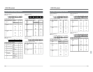
SYSTEM information-3
DATA0 10
Corresponding menu switches
No. Menu switch name Setting Set value
307 PAUSE/STILL/STP 1 SEC 0
TIME 10 SEC 1
30 SEC 2
1 MIN 3
2 MIN 4
3 MIN 5
4 MIN 6
5 MIN 7
311 AUTO PLAY AT OFF 0
TAPE BEGIN ON 1
314 PB/EE MODE STOP/FF/REW 0
STOP 1
328 EDIT POINT CLEAR DISABLE 0
ENABLE 1
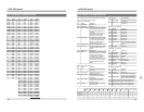
SYSTEM information-4
DATA0 20
Corresponding menu switches
No. Menu switch name Setting Set value
317 9PIN DEVICE ID JVC D80 0
JVC D860/D92/D95
1
DVW-A500 2
USE SETTING (382–385)
3
320 PREROLL TIME 0SEC 0
::
15SEC 15
323 PREROLL END STANDBY-ON 0
MODE
STILL 1
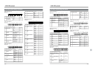
SYSTEM information-5
DATA0 40
Corresponding menu switches
No. Menu switch name Setting Set value
390 SWAP VTR SELECT AUTO 0
::
TYPE-9 9
391 SYNCRONIZATION DISABLE 0
ENABLE 1
393 SYNC GRADE ACCURATE 0
+/-1FRAME 1
+/-2FRAME 2
ROUGH 3
395 AUTO-EE RECORDER
ONLY
0
AUTO-EE 1
76543210
D1 307 307 307
D2 328 311 314
76543210
D1 005 002
D2 003 003
76543210
D1 312 302 301 300
D2 D95
76543210
D1 317 317
D2 323 320 320 320 320
76543210
D1 391 395
D2 390 390 390 390 393 393