


20
2 CONTROLS, CONNECTORS AND DISPLAYS
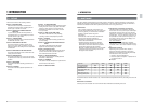
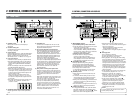
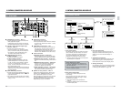
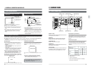
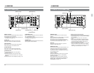
2-3 REAR PANEL
IN
CH1/2
CH1/2
CH3/4
CH3/4
OUT
IN OUT
1
2
Y
Y
R-Y
B-Y
B-Y
R-Y
IN
OUT
OUT
OFF
ON
75
LINE1
LINE2
SUPER
RS- 232C
COMPOSITE
LINE IN
REF
COMPONENT
COMPOSITE
REMOTE IN (9P)
REMOTE OUT (9P)
VIDEO CONTROL
CH1
CH2
CH3
CH4
CH2
CH3
CH4
CH1
IN
OUT
L
R
SERIAL V / ASERIAL V / A
AES / EBUAES / EBU
VIDEO
TIME CODE
AUDIO IN
AUDIO OUT
AUDIO MONITOR
13
10
11
12
17
14
15
16
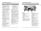
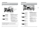
[AUDIO OUT] connectors
● Output analog audio signals.
● The output level can be set with menu switches
No. 228 to 231 <AUDIO OUT LEVEL>. Factory
setting is +4 dB.
[TIME CODE OUT] connector ... XLR
● Outputs a time code signal to the external time
code generator. LTC time code conforming to
the SMPTE/EBU standard can be output.
Outputs a time code signal during search if menu
switch No. 452 <SEARCH LTC> is set to ON (1).
Control connectors
Ⅲ [RS-232C] connector ... D-Sub 9-pin
Connect equipment conforming to the RS-232C
interface standard such as a personal computer.
Ⅲ [REMOTE IN (9P)] connector ... D-Sub 9-pin
Connect an RS-422 serial editing remote control
unit.
Ⅲ [REMOTE OUT (9P)] connector ... D-Sub 9-pin
Connect a VCR with RS-422 serial interface.
Connect to the other VCR’s [REMOTE IN]
connector to operate it from this VCR.
Ⅲ [VIDEO CONTROL] connector ... D-Sub 15-pin
Use to adjust the built-in TBC from an optional
video remote controller (Sony's BVR-50).
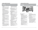
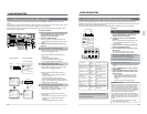
[SERIAL V/A OUT] connector ... BNC x 2
Outputs serial video/audio signals. When menu
switch No. 237 <EMBEDDED AUDIO> is set to
“OFF”, digital audio signals are not output.
When connecting to a VCR which is not equipped
to handle EMBEDDED AUDIO, set to “OFF”.
No signals are output if the optional SA-D95U
digital interface board is not installed.
[AES/EBU OUT] connector ... BNC x 2
● Outputs digital audio interface standard (AES/
EBU) digital audio signals.
Digital signals cannot be output if the optional
SA-D95U digital interface board is not installed.
[Y.R-Y.B-Y. OUT] component signal output
connector ... BNC x 3
● Outputs the component video signal.
Set menu switch No. 104 <CPN LEV./SETUP
(525)> to select MII (LOW), Bcam (HIGH) and
the presence of setup signals (NTSC only).
The default setting is Bcam with setup.
[COMPOSITE OUT] connectors
Ⅲ [LINE 1] connector
Outputs composite video signals.
Ⅲ [LINE 2 - SUPER] connector
Outputs composite video signals. When the
[ON SCREEN] switch on the sub panel is set
to “ON”, the time counter indication, operating
mode, etc. is superimposed on the screen
image. The menu switch items are shown in the
Menu Switch Setting mode.
Adjustment parameters and current settings are
displayed on screen when the video parameters
are being adjusted.
[AUDIO MONITOR] connectors
● Outputs the audio signal selected with the front
panel's [AUDIO MONITOR] button and audio
signal select buttons.
● The output level can be set with menu switches
No. 232 to 233 <AUDIO MON LEVEL>. Factory
setting is +4 dB.
21
1
4
5
2
3
M
H
F
S
CONDITION
CONDITION
CTL
UB
M
H
F
S
M
H
F
S
M
H
F
S
CONDITION
TC
M
H
F
S
M
H
F
S
M
H
F
S
2 CONTROLS, CONNECTORS AND DISPLAYS
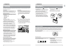
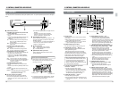
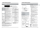
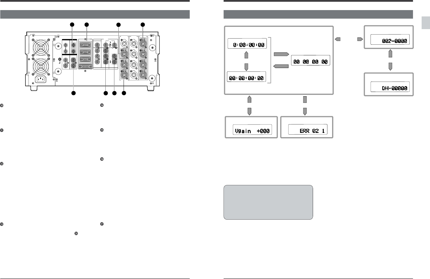
2-4 COUNTER DISPLAY
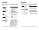
3. Hour meter data display
Hour meter data (drum operation time) can be
displayed in the Menu Switch Setting mode. For
details, refer to “Hour meter data display” on
page 39.
4. Video/audio control display.
Shows video and audio control adjustment items.
Select with the jog dial. Pressing the [VCON]
button restores the Tape Counter Display mode.
5. Warning code display
If a malfunction occurs, the corresponding warning
code is automatically displayed. For details, refer
to “Warnings with Indicators” on page 145.
1. Tape counter display
The display usually serves as a tape time counter
(hours, minutes, seconds, frames). CTL counter,
time code or user bits can be selected with the
front panel [COUNTER] switch. “NO TAPE” is
displayed if a cassette has not been loaded.
● The Menu Switch Setting mode is entered when
the [MENU] button is pressed.
How to reset the CTL counter
● Pressing the [RESET] button resets the CTL
counter to “0:00:00:00”. Time codes and user
bits cannot be reset.
● The CTL counter is also reset to “0:00:00:00”
when the cassette is ejected.
2. Menu switch setting display
To select menu functions and perform menu
switch setting.
Menu functions and menu switch items can be
changed with the jog dial. See page 31 “Menu
Switch Setting” for details.
● The counter display shows symbols and
numbers.
● Pressing the [MENU] button restores the Tape
Counter Display mode.
Menu setting display
[MENU]
button
Tape counter
When the VCR malfunctions
[VCON] button
[COUNTER]
button
or
[SHIFT]+[COUNTER]
buttons
[COUNTER] button
Time code
[SHIFT]+[COUNTER]
buttons
User bits
Video control display
Warning display
Hour meter display
Jog dial