


130
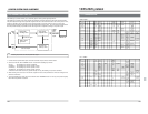
13-2 RS-232C Commands
13 RS-232C protocol
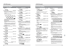
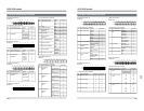
TxD DB
RxD 3* 3* 3* 3*
10H 1H 10M 1M
3* 3* 3* 3*
10S 1S 10F 1F
TxD DA
RxD 3* 3* 3* 3*
10H 1H 10M 1M
3* 3* 3* 3*
10S 1S 10F 1F
TxD DE
RxD 3* 3* 3* 3*
10H 1H 10M 1M
3* 3* 3* 3*
10S 1S 10F 1F
TxD DD
RxD ** ** ** **
TxD DC
RxD ** ** ** **
10H 1H 10M 1M
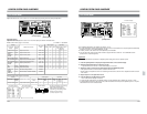
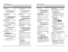
DA: In Data Sense Basic Table
Shows the set IN point.
•Values after the first RxD byte from 0 to 9 are
expressed in ASCII code.
DB: Out Data Sense Basic Table
Shows the set OUT point.
•Values after the first RxD byte from 0 to 9 are
expressed in ASCII code.
DB: Panel Switch Sence JVC-1 Table
Shows the various settings on the front panel.
• For an explanation of the meaning of each bit,
refer to “EC:Panel Switch Preset”.
DC: Current TC UB Sense Basic Table
Shows the current TC UB data.
•Values after the first RxD byte from 0 to f (HEX)
are expressed in ASCII code.
DD: JVC Status Sense Basic/JVC-1 Table
Shows the VCR status.
• For an explanation of the meaning of each bit,
refer to “Sense command details”.
DE: Current Sub Tc Sense Basic Table
Shows the current SUB-TC time data.
•Values after the first RxD byte from 0 to 9 are
expressed in ASCII code.
DF: Current Sub UB Sense Basic Table
Shows the current SUB TC UB data.
•Values after the first RxD byte from 0 to f (HEX)
are expressed in ASCII code.
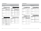
TxD DF
RxD ** ** ** **
10H 1H 10M 1M
** ** ** **
10S 1S 10F 1F
10H 1H 10M 1M
TxD E0 3* 3* 3* 3*
RxD 0A 0A 0A 0A 0A
10S 1S 10F 1F
3* 3* 3* 3*
0A 0A 0A 0A
TxD E2 40
RxD 0A 0A
** ** ** **
10S 1S 10F 1F
TxD DB
RxD ** ** ** **
DATA0 DATA1 DATA2 DATA3
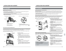
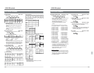
E0: TC Data Preset Basic Table
Presets the TC data.
•Values after the second TxD byte from 0 to 9 are
expressed in ASCII code.
Auxiliary commands
• [56: Clear] is valid for the second TxD byte or
later. All commands back to the first byte are
cleared.
• When [02: Error] occurs, [41: ClearError] is
valid. The previous command (one byte) is
cleared.
• [40: Enter] is valid for the second TxD byte or
later. Whatever has not yet been specified is
regarded as [30: Zero].
E1: TC UB Data Preset Basic Table
Presets the TC UB data.
•Values after the first RxD byte from 0 to f (HEX)
are expressed in ASCII code.
Auxiliary commands
• [56: Clear] is valid for the second TxD byte or
later. All commands back to the first byte are
cleared.
• When [02: Error] occurs, [41: ClearError] is
valid. The previous command (one byte) is
cleared.
• [40: Enter] is valid for the second TxD byte or
later. Whatever has not yet been specified is
regarded as [30: Zero].
E2: Counter Reset Basic JVC-1 Table
Resets the CTL counter.
Auxiliary commands
• [56: Clear] is valid for the second TxD byte. All
commands back to the first byte are cleared.
• When [02: Error] occurs, [41: ClearError] is
valid. The previous command (one byte) is
cleared.
• [40: Enter] is required for the second TxD byte.
10H 1H 10M 1M
TxD E1 ** ** ** **
RxD 0A 0A 0A 0A 0A
10S 1S 10F 1F
** ** ** **
0A 0A 0A 0A
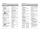
131
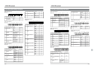
TxD E6 3* 3*
RxD 0A 0A 0A
TxD E7 3*
RxD 0A 0A
TxD E8 ** ** **
RxD 0A 0A 0A 0A
10S 1S 10F F
3* 3* 3* 3*
0A 0A 0A 0A
10H 1H 10M 1M
TxD E3 3* 3* 3* 3*
RxD 0A 0A 0A 0A A
10H 1H 10M 1M
TxD E4 3* 3* 3* 3*
RxD 0A 0A 0A 0A A
10S 1S 10F F
3* 3* 3* 3*
0A 0A 0A 0A
TxD E5 3* 3*
RxD 0A 0A 0A
13-2 RS-232C Commands
13 RS-232C protocol
E3: In Data Preset Basic/JVC-1 Table
Presets the IN point.
•Values after the second TxD byte from 0 to 9 are
expressed in ASCII code.
Auxiliary commands
• [56: Clear] is valid for the second TxD byte or
later. All commands back to the first byte are
cleared.
• When [02: Error] occurs, [41: ClearError] is
valid. The previous command (one byte) is
cleared.
• [40: Enter] is valid for the second TxD byte or
later. Whatever has not yet been specified is
regarded as [30: Zero].
E4: Out Data Preset Basic/JVC-1 Table
Presets the OUT point.
•Values after the second TxD byte from 0 to 9 are
expressed in ASCII code.
Auxiliary commands
• [56: Clear] is valid for the second TxD byte or
later. All commands back to the first byte are
cleared.
• When [02: Error] occurs, [41: ClearError] is
valid. The previous command (one byte) is
cleared.
• [40: Enter] is valid for the second TxD byte or
later. Whatever has not yet been specified is
regarded as [30: Zero].
E5: Edit Preset Basic Table
Selects the edit mode.
• Each bit is defined as follows:
76543 2 1 0
First byte 0 0 1 1 0 INS ASM Video
Second byte 0 0 1 1 0 TC Aud2 Aud1
Auxiliary commands
• [56: Clear] is valid for the second TxD byte or later.
All commands back to the first byte are cleared.
• When [02: Error] occurs, [41: ClearError] is valid.
The previous command (one byte) is cleared.
• [40: Enter] is invalid.
E6: Preroll TimePreset Basic Table
Sets the preroll time.
The set value should be less than 59 seconds.
If the preroll time is not set with this command, use
the VCR’s menu switch setting.
Auxiliary commands
• [56: Clear] is valid for the second TxD byte or later.
All commands back to the first byte are cleared.
• When [02: Error] occurs, [41: ClearError] is valid.
The previous command (one byte) is cleared.
• [40: Enter] is invalid.
E7: Timer Mode Select Basic/JVC-1 Table
Switches the current timer.
• Each bit is defined as follows:
765432 1 0
First byte 0 0 1 1 0 UB CTL TC
• CTL = 32, LTC = 31, LTC UB = 35
Auxiliary commands
• [56: Clear] is valid for the second TxD byte or later.
All commands back to the first byte are cleared.
• When [02: Error] occurs, [41: ClearError] is valid.
The previous command (one byte) is cleared.
• [40: Enter] is invalid.
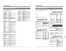
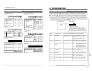
E8: Analog Data Set JVC-1 Table
Sets values for specified audio and video settings.
• Selects the setting item and sets the data as
shown below with the input values for the
second TxD byte or later.
The second byte: Selects the setting item (DATA0)
The third/fourth byte: Sets the data (DATA1, DATA2)
A/V Setting items DATA0 DATA1 DATA2
Tracking volume 20 00-FF —
Output video level 70 00-C0 —
Output chroma level 71 00-C0 —
Output video H phase 72 00-FF —
Output setup level 73 00-FF —
Output chroma phase 74 00-FF —
Output video V phase 75 03-0D —
Output system phase 76 03-0D —
Output SC phase 77
Low-order High-order
0000-011F
Output SCH phase 78 00-FF —
Output audio phase 79
Low-order High-order
20FE-D002
Auxiliary commands
• [56: Clear] is valid when [02: Error] occurs. All
commands back to the first TxD byte are cleared.
• When [02: Error] occurs, [41: ClearError] is valid.
The previous command (one byte) is cleared.
• [40: Enter] is invalid.