


12
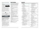
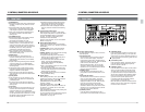
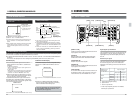
2-1 FRONT PANEL
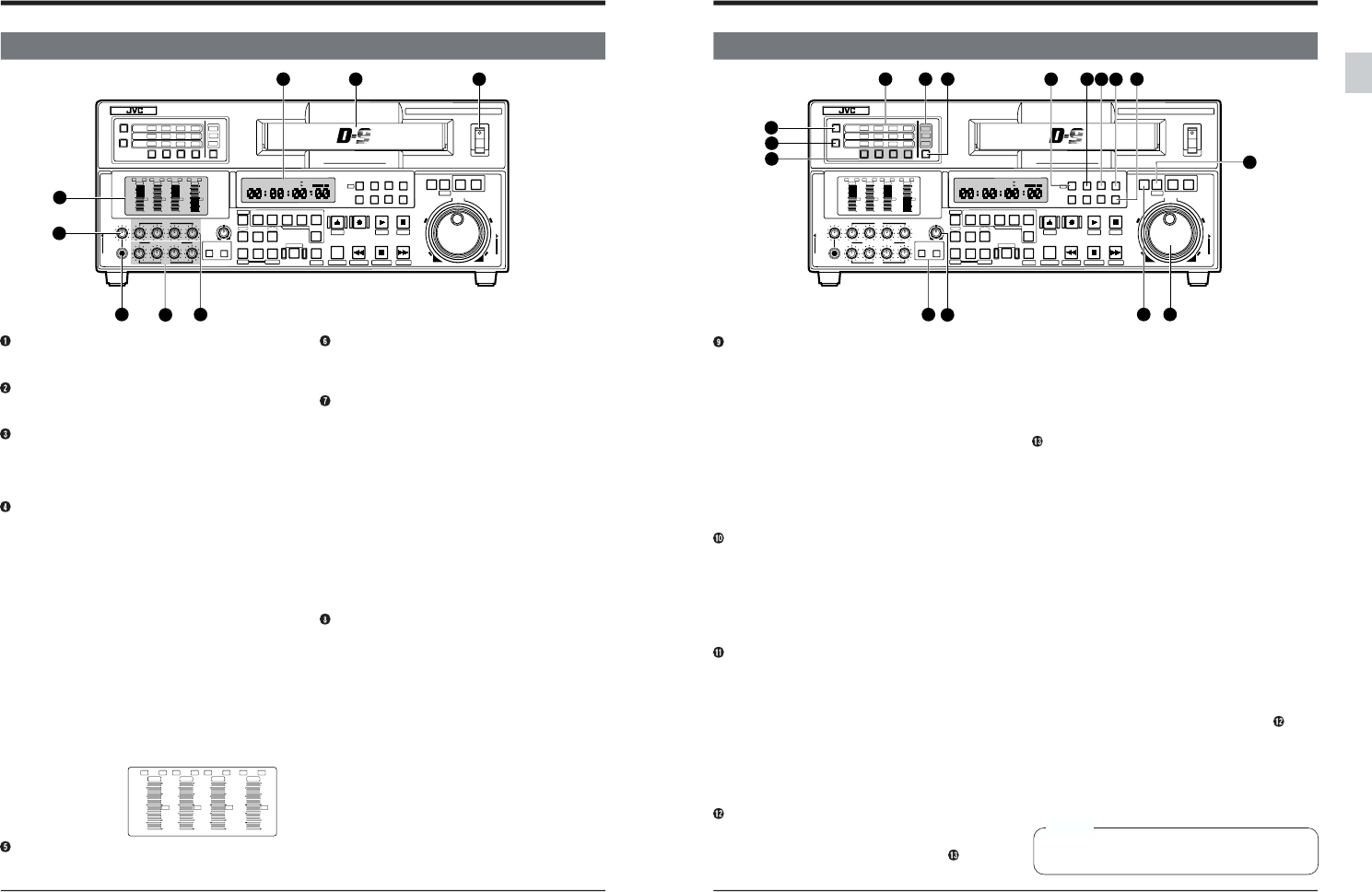
2 CONTROLS, CONNECTORS AND DISPLAYS
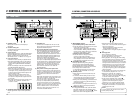
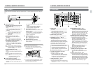
[POWER] switch
When power is ON, the counter display is
illuminated.
Cassette loading slot
S-VHS/VHS tapes cannot be used for either
recording or playback.
Counter display
Usually displays tape time. With the MENU button
pressed, it displays menu switch and hour meter
settings. Displays warning codes when an
abnormality occurs. For details, refer to page 21.
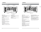
Level meter section
Indicates the audio recording or playback levels.
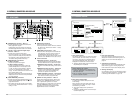
● The [CH4/TRACKING] meter can be switched
between tracking display and CH4 audio level
display with the [METER MODE TRACKING]
button.
● Audio Level Display mode can be selected with
the [METER MODE FINE] button.
● When the audio level adjust mode is set to Unity,
the [P] or [R] indicator in the upper section of the
meter lights. The [P] indicator lights in the Play
Volume mode and the [R] indicator lights in the
Record Volume mode.
When the audio level adjust mode is set to
Variable, the indicator goes out. You can use
the audio level adjust knobs to adjust the levels
in this mode.
● The audio reference level can be set with menu
switch No. 257 <AUD REF. SIGNAL LEV.>
(-20 dB or -18 dB).
[PHONES] headphone level adjust control
Adjusts signal level output from the [PHONES]
jack.
4
POWER
ON
I
OFF
O
M
H
F
S
REC
MENU
PLAY
PAUSE /STILL
REW
STOP
FF
EJECT
PHONES
CH1
CH2
CH3
CH4
REC
PLAY
PULL FOR VARIABLE
TRACKING
CH1
CH1
CH2
CH3
CH4/
TRACKING
SET
HOLD
PB
PB/EE
COUNTER
UB
CONDITION
AUDIO
INPUT
VIDEO
INPUT
AUDIO
MONITOR
PULL
RELEASE
RESET
VCON
REMOTE
TOP VIDEO AUDIO
OTHERSON SCREENTIME CODESERVO/SYS
USER
INSERT
STAND BY
PLAYER
SEARCH
VAR
P.PLAY
DA3
DA2
DA1VIDEO
ASSEM
IN
ENTRY
OUT
CANCEL
SHIFT
REVIEW
METER MODE
TRACKING
FINE
PREVIEW
AUTO EDIT
PREROLL
TC
RECORDER
DA4
VIDEO CASSETTE RECORDER
BR-D95U
STILL
X-1
REV
FWD
X1
CH2
CH3
CH4
CH1
CH2
CH3
CH4
CH1
CH2
CH3
CH4
SIF
SDI
AES/EBU
AUDIO INPUT / AUDIO MONITOR SELECT
LINE
CPN
L
ANALOG
R
PULL
RELEASE
CTL
P.READ
AUTO
OFF
V.VAR
REMOTE
PB/EE
16:9
TC
UB
DF
SERVO
GENCF
AP
525
OVER
–60
–2
–4
+2
+4
0
–40
–30
–20
–10
0
dB
dB
R
P
OVER
–60
–2
–4
+2
+4
0
–40
–30
–20
–10
0
dB
dB
R
P
OVER
–60
–2
–4
+2
+4
0
–40
–30
–20
–10
0
dB
dB
R
P
OVER
–60
–2
–4
+2
+4
0
–40
–30
–20
–10
0
dB
dB
R
P
625
Variable Motion
COMPONENT DIGITAL
3
2
1
5
6
7
8
CH1
CH2
CH3
CH4/
TRACKING
OVER
–60
–2
–4
+2
+4
0
–40
–30
–20
–10
0
dB
dB
R
P
OVER
–60
–2
–4
+2
+4
0
–40
–30
–20
–10
0
dB
dB
R
P
OVER
–60
–2
–4
+2
+4
0
–40
–30
–20
–10
0
dB
dB
R
P
OVER
–60
–2
–4
+2
+4
0
–40
–30
–20
–10
0
dB
dB
R
P
[PHONES] jack
Connect a set of headphones with a 6 mm-dia.
plug to listen to the audio channel selected with
the [AUDIO MONITOR] button.
[PLAY] audio playback level adjust knobs
Adjust the playback level for each channel (CH1 to
CH4). To adjust the audio playback level, pull out
the audio level adjust knobs. Turn clockwise to
increase the level and counterclockwise to lower it.
When audio level adjust knobs are pushed in, the
Unity mode is engaged. Turning the knobs in this
mode has no effect on the audio level.
There are two ways to adjust playback levels:
One way is to independently adjust playback levels
for each channel (CH1 to CH4 channels); the other
is to use the CH1 or CH3 adjust knob as a master
volume control and the CH2 or CH4 knob as a
balance control. You can select the method you
prefer with menu switch No. 216 <AUD PB
VOLUME MODE1>.
[REC] audio recording level adjust knobs
Adjust the recording level for each channel (CH1
to CH4). To adjust the audio recording level, pull
out the audio level adjust knobs. Turn clockwise
to increase the level and counterclockwise to
lower it.
When audio level adjust knobs are pushed in, the
Unity mode is engaged. Turning the knobs in this
mode has no effect on the audio level.
There are two ways to adjust recording levels:
One way is to independently adjust recording
levels for each channel (CH1 to CH4 channels);
the other is to use the CH1 or CH3 adjust knob as
a master volume control and the CH2 or CH4
knob as a balance control. You can select the
method you prefer with menu switch No. 215
<AUD REC VOLUME MODE1>.
13
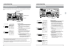
2-1 FRONT PANEL
2 CONTROLS, CONNECTORS AND DISPLAYS
POWER
ON
I
OFF
O
M
H
F
S
REC
MENU
PLAY
PAUSE /STILL
REW
STOP
FF
EJECT
PHONES
CH1
CH2
CH3
CH4
REC
PLAY
PULL FOR VARIABLE
TRACKING
CH1
CH1
CH2
CH3
CH4/
TRACKING
SET
HOLD
PB
PB/EE
COUNTER
UB
CONDITION
AUDIO
INPUT
VIDEO
INPUT
AUDIO
MONITOR
PULL
RELEASE
RESET
VCON
REMOTE
TOP VIDEO AUDIO
OTHERSON SCREENTIME CODESERVO/SYS
USER
INSERT
STAND BY
PLAYER
SEARCH
VAR
P.PLAY
DA3
DA2
DA1VIDEO
ASSEM
IN
ENTRY
OUT
CANCEL
SHIFT
REVIEW
METER MODE
TRACKING
FINE
PREVIEW
AUTO EDIT
PREROLL
TC
RECORDER
DA4
VIDEO CASSETTE RECORDER
BR-D95U
STILL
X-1
REV
FWD
X1
CH2
CH3
CH4
CH1
CH2
CH3
CH4
CH1
CH2
CH3
CH4
SIF
SDI
AES/EBU
AUDIO INPUT / AUDIO MONITOR SELECT
LINE
CPN
L
ANALOG
R
PULL
RELEASE
CTL
P.READ
AUTO
OFF
V.VAR
REMOTE
PB/EE
16:9
TC
UB
DF
SERVO
GENCF
AP
525
OVER
–60
–2
–4
+2
+4
0
–40
–30
–20
–10
0
dB
dB
R
P
OVER
–60
–2
–4
+2
+4
0
–40
–30
–20
–10
0
dB
dB
R
P
OVER
–60
–2
–4
+2
+4
0
–40
–30
–20
–10
0
dB
dB
R
P
OVER
–60
–2
–4
+2
+4
0
–40
–30
–20
–10
0
dB
dB
R
P
625
Variable Motion
COMPONENT DIGITAL
20
19
21
22
18 17 16 15 14
12
11
9
10
13
23
24
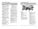
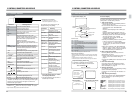
[METER MODE] buttons
Ⅲ [TRACKING] tracking meter mode button
● Press this button to switch between CH-4 audio
level meter and tracking meter.
This button lights or blinks when the tracking
meter is selected. Blinking indicates that auto
tracking is OFF. (When setting menu switch No.
005 <AUTO TRACKING> to “OFF”)
Ⅲ [FINE] fine meter mode button
● Press this button to change the display
accuracy of the audio level meter.
When the [FINE] indicator is illuminated, the
meter display is in Fine mode. More precise
level adjustment is possible in this mode.
[TRACKING] adjust knob
Manually adjusts tracking during playback.
After setting the [CH4/TRACKING] meter to
Tracking Display mode with the [TRACKING
METER MODE] button, adjust this knob until the
meter swings to the maximum level.
*To manually adjust tracking, set menu switch
No. 005 <AUTO TRACKING> to “OFF (0)”.
[SEARCH] button
● Starts search at the search speed set by the
search dial.
● In the Menu Switch Setting mode, the menu
switch setting can be changed by turning the
jog dial while keeping this button pressed.
● During time code presetting, preset data can be
changed by turning the jog dial while keeping
this button pressed.
● Use this button to change the fixed time cue up
data or the video control adjust parameters.
[VAR/P.PLAY] button
●To engage the Variable mode, press this button.
The button will light when the Variable mode is
engaged. In this mode, you can use the search
dial to control slow-motion playback speed.
●Press this button while holding the [SHIFT]
button down. The button blinks and the Program
Play mode is engaged.
*Before engaging the Program Play mode,
engage the Still or Stop mode.
For details, refer to “Program Playback” on page
85.
Search/jog dials
Turn for search/jog operation.
The outer dial serves as a search control.
The inner dial serves as a jog control.
●During playback, turn the jog dial while holding
the [PLAY] button down to increase or decrease
the playback speed. Playback speed corre-
sponds to the speed with which you turn the dial.
Turning the dial clockwise allows you to increase
playback speed to up to 2 times normal speed.
Turning it counterclockwise allows you to de-
crease playback speed until tape running stops.
If you stop turning the jog dial, normal playback
speed is restored.
●In the Variable mode, turn the outer search dial
for variable slow playback from -1x to +1x.
●When menu switch No. 301 <DIRECT
SEARCH> is set to “OFF”, hold the [PLAY]
button down and turn the search dial during play
to execute variable slow playback.
●In the Program Playback mode, hold the
[VAR/P.PLAY] button down and turn the inner
jog dial to set the initial speed for program
playback or to vary program playback speed.
●The jog dial is also used to select items when
setting the menu switches or to set data when
presetting the time code.
Caution
To use the search dial, first set it to the “STILL”
position (with power ON).