


24
2-5 ON-SCREEN DISPLAY
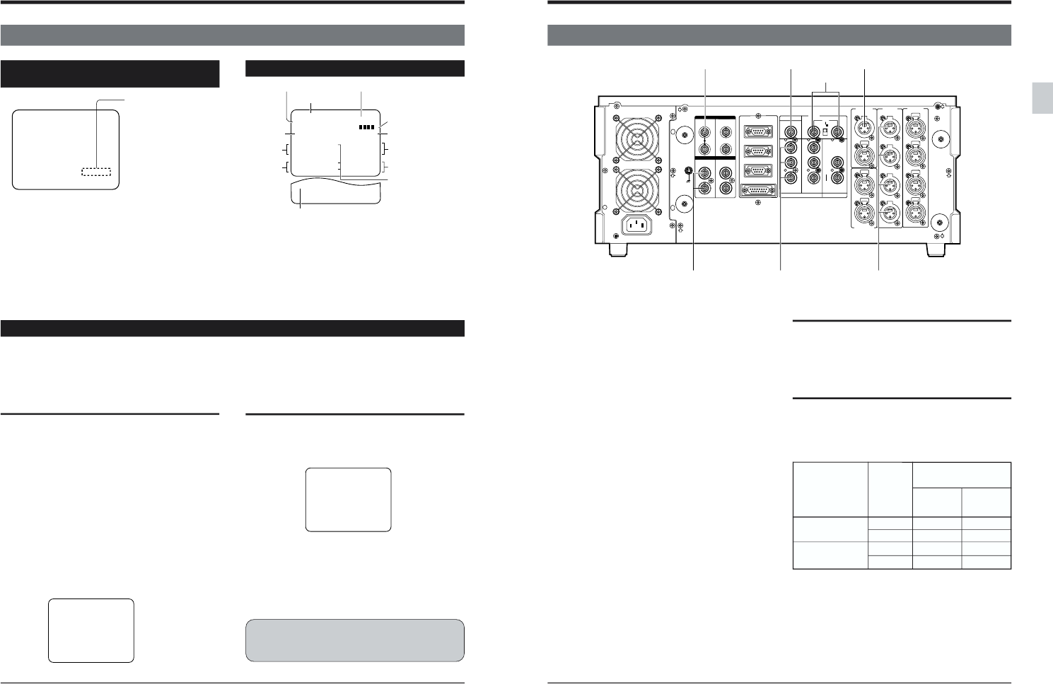
2 CONTROLS, CONNECTORS AND DISPLAYS
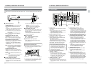
Operation mode display in the Variable-
motion mode
Noiseless slow-motion playback is available at
speeds of -1.0 to +1.0 times normal.
● Variable-motion playback at speeds outside this range
(from -1.0 times to +1.0 times) results in a distorted
picture.
● When variable-motion playback is performed at speeds
outside the range from -1.0 times to +1.0 times, “!”
appears with the operation mode on the on-screen
display.
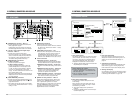
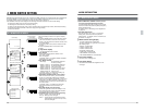
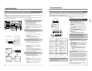
The “MUTING” or “CONDITION ALARM” can be shown on screen to make it easy to check VCR operating status
on the monitor connected to the [LINE 2- SUPER OUT] connector.
Ⅲ To display MUTING/CONDITION ALARM on screen, set menu switch No. 512 <MUTING/ALARM MESSAGE>
to “ON (1)”.
This can also be displayed even when setting the [ON SCREEN] switch on the sub panel to OFF.
Error rate degradation can also be checked with
the [CHANNEL CONDITION] indicator on the
front panel (refer to page 22).
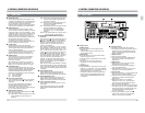
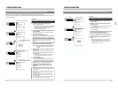
Editing screen display
CTL -0:00:00:01
Operation mode
●-1.0 times slow-motion
playback: VAR -1.0
●-1.5 times slow-motion
playback: !VAR -1.5
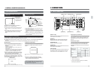
Monitor screen
● Tape remain is shown when the remaining time is less
than 25 minutes (approx.).
● This display automatically appears whenever an editing-
related button is pressed (such as selecting the edit mode).
(With menu switch No. 513 <EDIT ON SCREEN> set to
“ON”)
● When menu switch No. 513 <EDIT ON SCREEN> is set
to “ON”, press the [STANDBY] + [SHIFT] to switch the
edit screen ON/OFF.
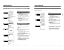
MUTING/CONDITION ALARM display
CONDITION ALARM
(Menu switch No. 512 <MUTING/ALARM MESSAGE> set to “ON
(1)”)
CONDITION ALARM display
If video head output (error rate) is degraded during
playback, the “CONDITION ALARM” is shown on
screen.
● When the “CONDITION ALARM” is displayed,
perform manual tracking adjustment or cleaning
with the dedicated head cleaning tape.
MUTING display
● This unit outputs black signals from the built-in
signal generator via the <LINE 2 - SUPER OUT>
connector.
• In Record or EE mode:
When no video signal is input or input signals do not
contain a sync signal
• In Play mode:
When there are no recorded signals (no control signal
recorded) on the tape being played back (With menu
switch No. 120 <NO CTL MUTING> set to “ON”)
● When the input signal is a black signal or when a
tape on which a black signal is recorded is played
back, the monitor’s screen will be black.
To differentiate between the types of black screen
described above, “MUTING” appears on the screen
when the black screen is due to black signals output
from the built-in signal generator.
(Menu switch No. 512 <MUTING/ALARM MESSAGE> set to “ON (1)”)
MUTING
Monitor screen
R:SHTL STIL
DUR.
P:STOP
CTL
CTL
0:01:48:00
SPLIT
- :15:01
V•A1•A2•A3•A4•TC
Editing mode
Recorder current time
Tape remain
Player edit point
Player operation mode Recorder operation mode
Player
current time
Audio
sprit time
Duration
Recorder edit point
Edit point registration
indications:
P
IN '
OUT
R
IN '
OUT'
:43:04
-0:00:51:03
0:01:48:00
0:01:31:04
0:00:00:00
0:00:43:04
EF
+030
P
R
Variable mode
tape speed
R
IN
OUT
Show edit points
registered by pressing
the [ENTRY] button.
25
IN
CH1/2
CH1/2
CH3/4
CH3/4
OUT
IN OUT
1
2
Y
Y
R-Y
B-Y
B-Y
R-Y
IN
OUT
OUT
OFF
ON
75
LINE1
LINE2
SUPER
RS- 232C
COMPOSITE
LINE IN
REF
COMPONENT
COMPOSITE
REMOTE IN (9P)
REMOTE OUT (9P)
VIDEO CONTROL
CH1
CH2
CH3
CH4
CH2
CH3
CH4
CH1
IN
OUT
L
R
SERIAL V / ASERIAL V / A
AES / EBUAES / EBU
VIDEO
TIME CODE
AUDIO IN
AUDIO OUT
AUDIO MONITOR
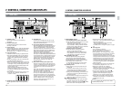
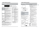
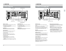
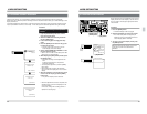
3 CONNECTIONS
3-1 INPUT CONNECTIONS
[SERIAL V/A IN]
Install the optional SA-D95U digital interface board to
input signals to this connector.
[AUDIO IN]
Set the audio input reference level with menu
switches No. 224 to 227 <AUDIO IN LEVEL>.
[COMPONENT IN]
Accepts component video signals.
[AES/EBU IN]
Install the optional SA-D95U digital interface board to
input signals to this connector.
[TIME CODE IN]
To record the time code input from this connector, set
the [INT/EXT] switch on the sub panel to “EXT” and
menu switch No. 409 <EXT REGEN TC> to “LTC”.
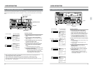
Digital signal synchronization
The input digital signal must be synchronized with the
video signals. To do this, input sync signals to the
digital signal output unit and the [REF] connector of
this unit.
Reference sync signal
The servo system of this unit automatically selects
the reference signal as shown in the table below
depending on the setting of the menu switch and the
operation.
[REF]
[TIME CODE IN][COMPOSITE IN][SERIAL V/A IN]
[COMPONENT IN] [AUDIO IN][AES/EBU IN]
Setting of menu
switch N. 003
<SYNC SELECT>
AUTO
EXT
Input sync signal
Operation
Video input [REF] input
Recording r
Playback r
Recording rR
Playback r
R
: Synchronizes (highest priority)
r
: Synchronizes.
: Does not synchronize.
• If video input and [REF] input are not available,
internal sync is performed.