


128
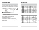
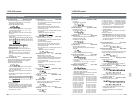
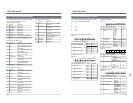
B5: Fwd Shuttle Key Basic/JVC-1 Table
Shuttle search playback in the forward direction.
• Specify the Fwd Shuttle Mode. The speed is
specified by the second byte.
• Specify the adjustment speed.
• The second TxD byte consists of numeric data
and is expressed with “30”, “31”, “32” ... “38”,
“39”, “3A”, “3B” and “3C”.
• When invalid data is received, the VCR returns
“02: Error”.
• The speeds corresponding to each value are
shown below.
Data 30 31 32 33 34 35 36 37 38
Speed Still 0.03 0.09 0.20 0.50 1 2 4 6
39 3A
10 17 or 32
Data 3B 3C
Adjustment speed -10% +10%
Auxiliary commands
• [56: Clear] is valid for the second TxD byte or
later. All commands back to the first byte are
cleared.
•When [02: Error] occurs, [41: ClearError] is
valid. The previous command (one byte) is
cleared.
[40: Enter] has no effect.
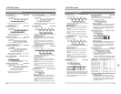
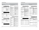
B6: Rev Shuttle Key Basic/JVC-1 Table
Shuttle search playback in the reverse direction.
Specify the Fwd Shuttle Mode. The speed is
specified by the second byte.
Specify the adjustment speed.
• The second TxD byte consists of numeric data
and is expressed with “30”, “31”, “32” ... “38”,
“39”, “3A”, “3B” and “3C”.
• When invalid data is received, the VCR returns
“02: Error”.
• The speeds corresponding to each value are
shown below.
Data 30 31 32 33 34 35 36 37 38
Speed Still 0.03 0.09 0.20 0.50 1 2 4 6
39 3A
10 17 or 32
Auxiliary commands
• [56: Clear] is valid for the second TxD byte or later.
All commands back to the first byte are cleared.
• When [02: Error] occurs, [41: ClearError] is valid. The
previous command (one byte) is cleared.
• [40: Enter] has no effect.
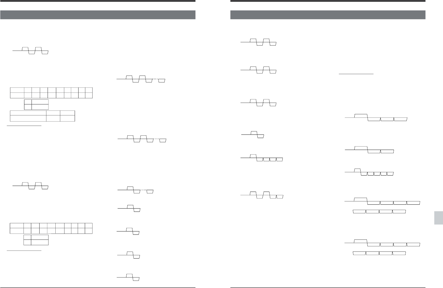
TxD B5 3*
RxD 0A 0A
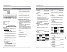
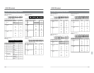
C0: Auto Edit Key Basic Table
Executes Auto Edit on the VCR.
• The editing channel must be selected with [E5/
E9: Edit Preset].
• Use with [FA: Rec Request].
•
Set the preroll time with [E6: Preroll Time Preset].
• When preroll time is not specified, the VCR’s
menu setting is used.
• The VCR returns [01: Complete] after Auto Edit
is complete.
[0B: NAK] is returned to the player.
C1: Preview Key Basic Table
Execute Preview on the VCR.
• The editing channel must be selected with [E5/
E9: Edit Preset].
• Use with [FA: Rec Request].
•
Set the preroll time with [E6: Preroll Time Preset].
• When preroll time is not specified, the VCR’s
menu setting is used.
• The VCR returns [01: Complete] after Preview is
complete.
[0B: NAK] is returned to the player.
C2: Review Key Basic Table
Execute Review on the VCR.
• [C0: Auto Edit] must be complete.
• Set the preroll time with [E6: Preroll Time Preset].
• When preroll time is not specified, the VCR’s
menu setting is used.
• The VCR returns [01: Complete] after Review is
complete.
[0B: NAK] is returned to the player.
C4: Full EE On Basic/JVC-1 Table
Checks VCR’s input signals.
The VCR returns [0B: NAK] to the player.
C5: EE Off Basic/JVC-1 Table
Releases EE check.
C8: Select EE On Basic Table
Checks the input signals to the editing channel
selected by [E5/E9: Edit Preset].
The VCR returns [0B: NAK] to the player.
C9: EE Off Basic Table
Releases EE check.
TxD B6 3*
RxD 0A 0A
13-2 RS-232C Commands
13 RS-232C protocol
TxD C4
RxD 0A
TxD C5
RxD 0A
TxD C8
RxD 0A
TxD C2
RxD 0A 01
TxD C9
RxD 0A
TxD FA C0
RxD 0A 0A 01
TxD FA C1
RxD 0A 0A 01
129
13-2 RS-232C Commands
13 RS-232C protocol
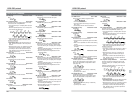
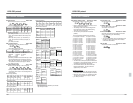
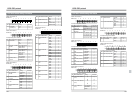
CA: Rec Key Basic/JVC-1 Table
Recording
Use with [FA: Rec Request].
The VCR returns [0B: NAK] to the player.
CB: Rec Pause Key Basic/JVC-1 Table
Recording is paused.
Use with [FA: Rec Request].
The VCR returns [0B: NAK] to the player.
CE: Edit On Key Basic Table
The channel selected with [E5: Edit Preset] is
engaged in the Edit mode.
Use with [FA: Rec Request].
The VCR returns [0B: NAK] to the player.
CF: Edit Off Key Basic Table
Stops the editing operation.
The VCR enters the Play mode after editing is
complete.
The VCR returns [0B: NAK] to the player.
D1: Device Type Request JVC-1 Table
Returns the model name of the connected VCR.
• Uses ASCII code to express “0” to “9”, “a” to “z”,
and “space”.
• For example, d = “64”, 9 = “39”, 5 = “35” and
space = “20” for the BR-D95.
D3: Memory SwitchSense JVC-1 Table
Recalls menu switch content.
• Refer to “Menu Switch setting” to find out more
about menu switch contents.
• Specify the address data you want to recall with
the second TxD byte.
The corresponding addresses are as follows.
01:Servo/System-1 information 08:System-2 information
10:System-3 information 20:System-4 information
40:System-5 information 88:System-6 information
89:System-7 information 90:System-8 information
87:System-9 information 09:System-10 information
91:System-11 information 92:System-12 information
94:System-14 information
0a:Video information-2 0b:Video information-3
0c:Video information-4 0d:Video-5 information
1b:Video-6 information 0e:Video-7 information
1e:Video-8 information 1c:Video-9 information
0f :Video-10 information 1f :Video-11 information
1d:Video-12 information 05:Audio-2 information
06:Audio-3 information 07:Audio-4 information
03:Audio-5 information 30:Audio-6 information
TxD FA CA
RxD 0A 0A
TxD FA CB
RxD 0A 0A
TxD FA CE
RxD 0A 0A
TxD CF
RxD 0A
TxD D1
RxD ** ** ** **
TxD D3 **
RxD 0A ** **
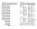
31: Audio-7 information 80: TimeCode-1 information
81:TimeCode-2 information 79:TimeCode-3 information
77:TimeCode-4 information 78:TimeCode-5 information
82:OnScreen-1 information 83: OnScreen-2 information
84: TBC information-1 86:TBC information-3
• The third and fourth RxD bytes express indi-
vidual bit information (Data1/Data2) for the
specified address.
• When invalid data is received, the VCR returns
“02: Error”.
Auxiliary commands
• When [02: Error] occurs, [56: Clear] is valid. All
commands back to the first TxD byte are cleared.
• When [02: Error] occurs, [41: ClearError] is valid.
The previous command (one byte) is cleared.
• [40: Enter] is invalid.
D4: Tape Remain Sense JVC-1 Table
Recalls remaining tape time information.
D6: Preroll Time Sense Basic Table
Shows the preroll time setting.
The VCR returns the value set by [E6: PrerollTime
Preset] or the value set with the VCR’s menu.
D7: Status Sense Basic/JVC-1 Table
Shows the VCR status.
• For an explanation of the meaning of each bit,
refer to “Sense command details”.
D8: Current TC Sense Basic/JVC-1 Table
Shows the current TC time data.
•Values after the first RxD byte from 0 to 9 are
expressed in ASCII code.
D9: Current CTL Sense Basic/JVC-1 Table
Shows the current CTL time data.
•Values after the first RxD byte from 0 to 9 are
expressed in ASCII code.
• The most significant bit at 10H expresses
“minus”.
TxD D7
RxD ** ** ** ** **
TxD D8
RxD 3* 3* 3* 3*
10H 1H 10M 1M
TxD D4
RxD 3* 3* 3*
1H 10M 1M
TxD D6
RxD 3* 3*
10S 1S
TxD D9
RxD 3* 3* 3* 3*
10H 1H 10M 1M
3* 3* 3* 3*
10S 1S 10F 1F
3* 3* 3* 3*
10S 1S 10F 1F