


148
15 APPENDIX
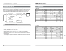
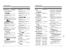
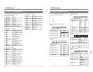
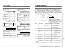
SA-D95U Digital Interface Board
Install in the BR-D95U. This is used to input and
output video and audio digital signals.
Precautions
● Do not use screws 8 mm or longer to secure the
rack mount adapter and slide rail inner members to
the VCR, as doing so may damage the printed
circuit boards inside the VCR.
● The handle on the rack mount adapter is only for
sliding the VCR in and out. Do not lift the VCR with
this handle.
●
When installing the VCR in a rack, make sure there
is sufficient clearance above and below the VCR for
heat radiation.
● Some racks may require that you mount the slide
rails in a particular way. If you have any questions,
consult the rack dealer.
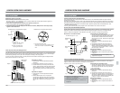
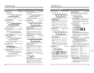
Rack Mount Adapter SA-K67
SA-K67 is a rack mount adapter used to mount this
unit on a 19" EIA standard rack.
Ⅲ Mount rail & bracket
When mounting the unit on a rack with the SA-
K67, a mount rail and mount bracket are also
required.
Recommended models:
● Acuryde Co., Ltd. 2038-22 (mount rail)
BK2038 (bracket)
Ⅲ Installation
1. Secure the rack mount adapter to the VCR with 6
M4 screws.
2. Secure the slide rail inner member to the VCR with
6 M4 screws.
3. Mount the slide rail outer members on the front
and rear ends of the rack using the bracket.
4. Pull out the rails in the slide rail outer members
until you hear a click.
5. Fit the right and left slide rails on the VCR into the
pulled-out rails and push them in together. The
rails will be blocked by right and left springs, so
press the springs with your fingers and push the
VCR further in.
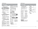
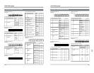
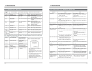
15-2 OPTIONAL ACCESSORIES15-1 Operation Button Combinations
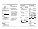
REC+PLAY Starts recording
REC+HOLD Starts recording current
adjustment (top menu 00E)
SET+HOLD Sets the top menu (00A — 00D)
(SET)
PLAY+FF 1.07x playback
PLAY+REW 0.93x playback
PLAY+ jog dial STILL — 2x playback
PLAY+ search dial Variable playback (0.9x to 1.1x
playback)
SEARCH+ jog dial Changes menu switch setting
value (menu switch setting)
Changes time code data (time
code setting)
Changes fixed time data (top
menu 00F)
STOP+STANDBY+ Starts head cleaning
REW+FF (No tape)
SET+RESET Registers counter memory point
SET+PREROLL Starts counter search
SHIFT+PREROLL Starts fixed time cue up
SHIFT+SEARCH Variable mode (Only the player
during swap editing)
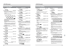
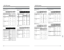
IN+ENTRY Registers the IN point
OUT+ENTRY Registers the OUT point
IN+OUT Duration display
IN+CANCEL Cancels the IN point
OUT+CANCEL Cancels the OUT point
IN+PREROLL Cues the IN point
OUT+PREROLL Cues the OUT point
IN+jog dial Corrects the IN point
OUT+jog dial Corrects the OUT point
IN+OUT+jog dial Corrects the duration
SHIFT+IN+ENTRY Registers the audio split point (IN
point)
SHIFT+IN Indicates the audio split point (IN
point)
SHIFT+IN+jog dial Corrects the audio split point (IN
point)
SHIFT+IN+CANCEL Cancels the audio split point (IN
point)
SHIFT+PREVIEW Review
SHIFT+AUTO EDIT Last edit
SHIFT+input video Switches input signal when
signal or audio signal menu switch No.371<INPUT
select button SELECT SAFETY> is set to “ON”.
SHIFT+MENU Opens the menu switch setting
display when menu switch No.
374 <MENU OPEN SAFETY> is
set to “ON”.
SHIFT+COUNTER ON/OFF switching of the counter
mode (user bits)
PLAYER+RECORDER Recorder and player
simultaneous operation mode
SHIFT+STANDBY Switches the edit on-screen
display ON/OFF
SHIFT+RECORDER Activates the learn function
CANCEL+AUTO EDIT To cancel the player and recorder
edit points as well as the audio
split point:
SHIFT+REC
Open the<STRIPING REC MENU>
SHIFT+P. PLAY Program Playback mode
P. PLAY+PLAY Starts the program playback.
P. PLAY+ jog dial Sets the program playback speed.
149
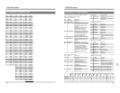
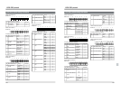
15-3 INDEX
15 APPENDIX
A.
Adjustment ............................................................118
Assemble editing...................................................104
Audio emphasis.......................................................74
Audio input connectors............................................19
Audio input switch ...................................................24
Audio monitor switch...............................................14
Audio output connectors .........................................20
Audio recording level...............................................71
Audio split editing..................................................112
Audio V. fade function.............................................80
C.
Cassette tape..........................................................11
Channel condition indicator.....................................22
Color frame servo setting......................................105
Condensation..........................................................10
Counter memory .....................................................86
Counter switch ........................................................21
D.
Diagnosis connector................................................18
Direct access...........................................................33
Drop frame ..............................................................98
Dubbing loop function ...........................................122
E.
Editing system phase adjustment .........................117
Error conceal...........................................................80
Error correction .......................................................80
Extra line playback..................................................88
Extra line recording .................................................87
F.
Fine meter mode button..........................................13
Fixed time cue up function ......................................91
H.
Head cleaning .........................................................11
Hour meter ..............................................................39
I.
Insert editing..........................................................104
L.
Last edit.................................................................113
M.
Main code..............................................................101
Masking setting .......................................................64
Match frame ............................................................58
Meter mode setting button ......................................15
Menu switch list.......................................................40
Menu switch setting.................................................28
Menu switch setting button......................................15
Menu switch setting contents..................................43
Monitor output connector section............................26
Motion memory function........................................114
Mute/alarm condition display...................................24
Multi cue-up function...............................................92
N.
Non-drop frame.......................................................97
O.
Optional equipment...............................................148
Operation buttons....................................................12
Operation mode lock...............................................65
P.
Power switch...........................................................12
Pre-read function ..................................................115
Preview switcher ...................................................116
Program playback ...................................................85
R.
Recording current adjustment.................................38
Reference sync signal.............................................25
Remote connector...................................................20
Remote button.........................................................14
Repeat playback .....................................................86
S.
Search/jog dial ........................................................13
Simplified playback speed adjustment function ......81
Simultaneous operation ..........................................90
Slow play.................................................................24
Standby ON/OFF ....................................................16
Striping rec function ................................................94
Subcarrier phase adjustment ................................121
Sub code...............................................................102
Sub time code display.............................................96
Sub time code playback........................................102
Sub time code recording .......................................102
Swap editing .........................................................107
Synchronized running mode ...................................81
T.
Time code display ...................................................96
Time code generator setting buttons ......................18
Time code playback ..............................................101
Time code presetting...............................................97
Time code recording ...............................................99
Time code setting switch section ............................18
Top menu................................................................28
U.
User page................................................................34
User bit auto preset function ...................................63
V.
Variable-motion editing .........................................113
Variable slow playback ...........................................83
Video control connector ..........................................27
Video input connectors ...........................................25
Video input switch ...................................................14
Video phase adjustment........................................118
W.
Warning.................................................................145