146
14 TROUBLESHOOTING
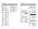
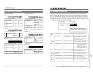
14-1 WARNINGS WITH INDICATORS
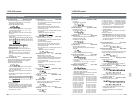
Warning On-screen display Warningcode information Behavior and actions to be taken
code
41 1 CASSETTE EJECT Cassette does not come
(AUTO OFF)
FAILURE out in Eject.
56 1~ TAPE DEFECTIVE Tape defect.
56 9 Tape loose
57 1~ END LEADER Tape end sensor abnormal.
57 2 DETECTION
58 1~ BEGIN LEADER Tape beginning sensor
58 2 DETECTION abnormal.
70 1 DRUM MOTOR Drum stops motion.
(AUTO OFF)
FAILURE
71 1 CAPSTAN MOTOR Capstan stops its motion.
(AUTO OFF)
FAILURE
72 1~ SUP REEL MOTOR Supply reel motor motion
72 8 FAILURE abnormal.
(AUTO OFF)
73 1~ TU REEL MOTOR Takeup reel motor motion
73 8 FAILURE abnormal.
(AUTO OFF)
Behavior:Only warning indicator is active.
Action: Consult your local JVC dealer.
When the MENU button is pressed, the
indication goes out.
Behavior: Stops, with no operation possible.
Action: Turn the power off and then on.
Behavior: Cassette ejected.
Action: If no abnormality is found in tape,
reload the cassette.
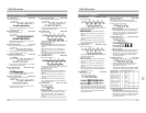
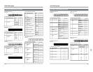
If there are any abnormalities when the self-diagnostics run after the power is turned on, the following warning indications ar
e
shown. Self-diagnostics are executed when menu switch No. 357 <DIAG AT POWER ON> is set to “ON”. The warning code is
shown in 6 digits. “ x ” mark shows unspecified.
Behavior: Stops, with no operation possible.
Action: Turn the power off and then on.
Behavior: Stops, with no operation possible.
Action: Turn the power off and then on.
Behavior: Stops, with no operation possible.
Action: Turn the power off and then on.
Behavior: Stops, with no operation possible.
Action: Turn the power off and then on.
Behavior: Tape is fast-forwarded. If tape
begin is still detected 3 seconds
later, cassette is ejected.
Action: Reload the cassette.
Behavior: Tape is rewound. If tape end is still
detected 3 seconds later, cassette
is ejected.
Action: Reload the cassette.
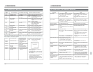
80xxxx CPU BUS FAILURE Signal communication
between VCR’s micro-
processors abnormal.
820100 EEPROM FAILURE EEPROM signal
820300 communication in VCR
abnormal.
840100 SYSCON REF FAILURE System controller reference
signal failure.
850100 M/S REF Mechanical controller
FAILURE reference signal failure.
860100 TC REF FAILURE Time code reference failure.
C0xxxx MECHA(NO TAPE) *1 Abnormal mechanical
FAILURE operation.
On-screen display
DIAG WARNING 800400
CPU BUS FAILURE
(PUSH MENU KEY)
* Serial digital signals are used in conformity
with SMPTE259M for video and with AES/
EBU for audio.
*1
If the C02XXX indicator appears when the
power is turned ON it means that
condensation has occurred. Press the
[MENU] button until the indicator goes out.
Once the indicator has gone out, you can
operate the unit as usual.
147
14 TROUBLESHOOTING
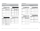
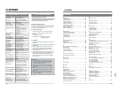
14-2 TROUBLES NOT TO BE WARNED BY INDICATORS
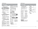
Symptoms Cause Action
Not operable
Not recordable
Playback impossible
On-screen display does
not come up
Noise appears on part of
the playback picture.
Tape counter does not run.
Menu setting cannot be
changed.
● Set [REMOTE] button to “LOCAL”.
● Set Menu switch No. 002 <OPERATION
LOCK> to “OFF”.
● Press [MENU] button to restore normal
mode.
● Set cassette’s protective slider to “REC”.
●Set menu switch No. 351 <PRE READ> to
“OFF”.
● S-VHS/VHS cassette not acceptable
● Connect monitor to [LINE2-SUPER OUT].
● Set [ON SCREEN] switch to ON.
● Clean the heads as instructed on page 11.
● Set menu switch No. 005 <AUTO TRACK-
ING> to “ON”.
If noise appears when set to “ON”, set to
“OFF” and perform manual tracking
adjustment.
● Set menu switch No. 112 <ECC MODE> to
“NORMAL”.
● Press [MENU] button and enter Tape
Counter mode.
●Set menu switch No. 00D <MENU LOCK>
to “OFF”.
● The [REMOTE] button is set to “Remote”.
● Menu switch No. 002 <OPERATION
LOCK > set to“ ON”
● Menu setting mode entered
● Protective slider on the cassette not at
“REC”
● Menu switch No. 351 <PRE READ> is set
to “VID-ON” or “AUD-ON”.
● S-VHS/VHS cassette in use
● Monitor not connected to [LINE2-SUPER
OUT]
● [ON SCREEN] switch on the sub panel set
to OFF.
● The heads are dirty.
● Menu switch No. 005 <AUTO TRACKING>
set to “OFF”.
● Menu switch No. 112 <ECC MODE> set to
“NO CONCEAL” or “NO CORRECTION”
● CTL counter does not run on a non-
recorded section of the tape as no CTL
signal is recorded on such a section.
● Counter is in Menu Switch Setting mode.
●Menu switch No. 00D <MENU LOCK> is
set to “ON”.
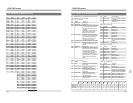
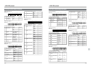
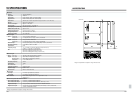
Input signal cannot be
switched.
The Menu Switch
Setting mode cannot be
engaged.
During playback, the on-
screen sub time code
indication does not
advance.
● Set menu switch No. 371 <INPUT SE-
LECT SAFETY> to “OFF” or press the
signal switch while pressing the [SHIFT]
button.
● Install the SA-D95U. Otherwise, digital
signals cannot be selected.
● Set menu switch No. 374 <MENU OPEN
SAFETY> to “OFF” or press the [MENU]
button while pressing the [SHIFT] button.
● Set menu switch No. 450 <SUB TC (VITC)
REC> to “ON” or menu switch No. 451
<VITC OUT SELECT> to “SUB TC”.
● Menu switch No. 371 <INPUT SELECT
SAFETY> is set to “ON”.
● The optional SA-D95U digital interface
board is not installed.
● Menu switch No. 374 <MENU OPEN
SAFETY> is set to “ON”.
● Menu switch No. 450 <SUB TC (VITC)
REC> is set to “OFF” and menu switch No.
451 <VITC OUT SELECT> is set to “OFF”
or “TC”.
● Sub time code is not recorded normally.


