


74
7 RECORDING
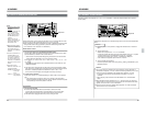
7-6 DIGITAL AUDIO SIGNAL INPUT/OUTPUT
Ⅲ This unit does not execute emphasis recording.
When digital audio signals containing emphasis information are input to this
unit, this unit automatically de-emphasizes these signals before recording.
The emphasis function is always OFF when digital audio signals are recorded
on this unit.
Ⅲ A sampling rate converter is provided for the BR-D95U’s AES/EBU input. This
enables input of both professional-standard and consumer-standard digital
signals with sampling frequencies of 48 kHz, 44.1 kHz and 32 kHz. However,
the following signals are muted and cannot be recorded. In this case, the
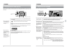
[AUDIO INPUT/AUDIO MONITOR SELECT] indicator blinks.
• Professional mode, CCIT J17
• Consumer mode, data mode ON
• Consumer mode, 4-channel mode
Note:
• Analog or digital audio output may not be clear when a tape whose audio
has been recorded on its audio channels with emphasis both ON and OFF
is played back on the BR-D85U/D80U/D51U/D50U/D750U/D350U
DIGITAL S VCR.
Ⅲ Digital audio signal output status bit
The sampling rate converter converts the digital audio signal output status bit
from this unit to professional mode signals with a sampling frequency of 48
kHz and emphasis OFF regardless of the type of input signals.
POWER
ON
I
OFF
O
M
H
F
S
REC
MENU
PLAY
PAUSE/ STILL
REW
STOP
FF
EJECT
PHONES
CH1
CH2
CH3
CH4
REC
PLAY
PULL FOR VARIABLE
TRACKING
CH1
CH1
CH2
CH3
CH4/
TRACKING
SET
HOLD
PB
PB/EE
COUNTER
UB
CONDITION
AUDIO
INPUT
VIDEO
INPUT
AUDIO
MONITOR
PULL
RELEASE
RESET
VCON
REMOTE
TOP VIDEO AUDIO
OTHERSON SCREENTIME CODESERVO/SYS
USER
INSERT
STAND BY
PLAYER
SEARCH
VAR
P.PLAY
DA3
DA2
DA1VIDEO
ASSEM
IN
ENTRY
OUT
CANCEL
SHIFT
REVIEW
METER MODE
TRACKING
FINE
PREVIEW
AUTO EDIT
PREROLL
TC
RECORDER
DA4
VIDEO CASSETTE RECORDER
BR-D95U
STILL
X-1
REV
FWD
X1
CH2
CH3
CH4
CH1
CH2
CH3
CH4
CH1
CH2
CH3
CH4
SIF
SDI
AES/EBU
AUDIO INPUT / AUDIO MONITOR SELECT
LINE
CPN
L
ANALOG
R
PULL
RELEASE
CTL
P.READ
AUTO
OFF
V.VAR
REMOTE
PB/EE
16:9
TC
UB
DF
SERVO
GENCF
AP
525
OVER
–60
–2
–4
+2
+4
0
–40
–30
–20
–10
0
dB
dB
R
P
OVER
–60
–2
–4
+2
+4
0
–40
–30
–20
–10
0
dB
dB
R
P
OVER
–60
–2
–4
+2
+4
0
–40
–30
–20
–10
0
dB
dB
R
P
OVER
–60
–2
–4
+2
+4
0
–40
–30
–20
–10
0
dB
R
P
625
Variable Motion
COMPONENT DIGITAL
75
1
2
3
POWER
ON
I
OFF
O
M
H
F
S
REC
MENU
PLAY
PAUSE/ STILL
REW
STOP
FF
EJECT
PHONES
CH1
CH2
CH3
CH4
REC
PLAY
PULL FOR VARIABLE
TRACKING
CH1
CH1
CH2
CH3
CH4/
TRACKING
SET
HOLD
PB
PB/EE
COUNTER
UB
CONDITION
AUDIO
INPUT
VIDEO
INPUT
AUDIO
MONITOR
PULL
RELEASE
RESET
VCON
REMOTE
TOP VIDEO AUDIO
OTHERSON SCREENTIME CODESERVO/SYS
USER
INSERT
STAND BY
PLAYER
SEARCH
VAR
P.PLAY
DA3
DA2
DA1VIDEO
ASSEM
IN
ENTRY
OUT
CANCEL
SHIFT
REVIEW
METER MODE
TRACKING
FINE
PREVIEW
AUTO EDIT
PREROLL
TC
RECORDER
DA4
VIDEO CASSETTE RECORDER
BR-D95U
STILL
X-1
REV
FWD
X1
CH2
CH3
CH4
CH1
CH2
CH3
CH4
CH1
CH2
CH3
CH4
SIF
SDI
AES/EBU
AUDIO INPUT / AUDIO MONITOR SELECT
LINE
CPN
L
ANALOG
R
PULL
RELEASE
CTL
P.READ
AUTO
OFF
V.VAR
REMOTE
PB/EE
16:9
TC
UB
DF
SERVO
GENCF
AP
525
OVER
–60
–2
–4
+2
+4
0
–40
–30
–20
–10
0
dB
dB
R
P
OVER
–60
–2
–4
+2
+4
0
–40
–30
–20
–10
0
dB
dB
R
P
OVER
–60
–2
–4
+2
+4
0
–40
–30
–20
–10
0
dB
dB
R
P
OVER
–60
–2
–4
+2
+4
0
–40
–30
–20
–10
0
dB
dB
R
P
625
Variable Motion
COMPONENT DIGITAL
CONDITION
CTL
REMOTE
TC
UB
GEN
525
625
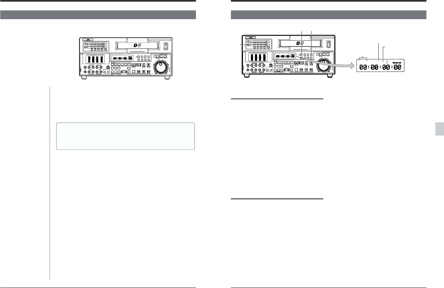
8 PLAYBACK
8-1 PREPARATION FOR PLAYBACK
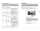
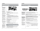
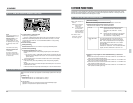
Front panel switch setting
1. Select the audio monitor output.
Select the audio monitor output from the rear
panel [AUDIO MONITOR OUT] connectors or the
front panel [PHONES] jack.
• For the selection procedure, refer to “Audio
monitor output selection” on page 70.
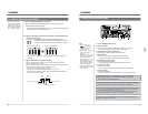
2. Set the tape counter mode.
Set the time data to be shown on the counter
display and the on-screen display. “CTL”, “TC” or
“UB” will be shown on the counter display.
3. Engage the Remote mode.
To operate this unit locally, press the [REMOTE]
button so that the [REMOTE] indicator on the
counter display goes out.
To operate this unit via the RS-422 or RS-232C
serial remote interface, press the [REMOTE]
button so that the [REMOTE] indicator lights.
Menu switch setting
Set the menu switches as required.
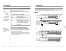
● Reference sync signal items
• Select the reference sync system.
No. 003 <SYNC SELECT> ..... Page 43
Set to “EXT” to synchronize with an external sync
signal.
● Tracking adjustment selection
• Auto tracking/manual tracking selection
No. 005 “AUTO TRACKING” .... Page 43
● Video items
• Component video output level selection (NTSC
only)
No. 104 <CPN LEV./SETUP (525)> ... Page 44
• Error correction mode selection
No. 112 <ECC MODE> ... Page 45
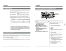
Counter mode
indicators
● Audio items
• Audio V. fade function selection
Select whether audio noise in transitions should
be reduced or not.
No. 214 <PBV. FADE> ..... Page 50
• Audio output level adjustment mode selection
Select automatic or manual adjustment.
No. 216 <AUD PB VOLUME MODE 1> ... Page 51
• Set the output to CH3 and CH4 when playing
back a tape with two-channel audio (CH1 and
CH2).
No. 223 CH3/4 OUT SEL AT 2CH ... Page 52
• Audio output level setting
Select the reference output level for the audio
output connectors (CH1 to CH4 ) from +4 dB, 0
dB and -6 dB.
No. 228 to No. 231 <AUDIO OUT LEVEL CH1 —
CH4> ... Page 52
• Audio monitor output level setting
Select the reference output level for the L and R
audio monitor output channels from +4 dB, 0 dB
and -6 dB.
No. 232 to No. 233 <AUDIO MON LEVEL LCH —
RCH>
● Auto Play mode selection
Set whether the tape is automatically played back
from the beginning or not.
● Output picture selection when playback starts
Select the output picture that will be displayed
until the servo has stabilized after starting play
back.
No. 368 <STARTING PIC FREEZE> ... Page 57
● Setting the video signal vertical blanking period
masking
No. 601 <V. BLANK MASK> ..... Page 64
When this unit is
synchronized externally
REMOTE indicator
(when using the
remote control unit)