


42
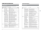
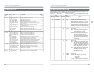
Functional No Names Description Reference
group Page
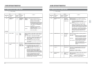
SYSTEM 381 JOG FEELENG (LOCAL) Selects jog dial operation response level ......................................................... 59
382 9 PIN ID
Ⅲ
---(1ST) Sets the first digit of the ID code ...................................................................... 59
383 9 PIN ID-
Ⅲ
--(2ND) Sets the second digit of the ID code................................................................. 59
384 9 PIN ID--
Ⅲ
-(3RD) Sets the third digit of the ID code ..................................................................... 59
385 9 PIN ID---
Ⅲ
(4TH) Sets the fourth digit of the ID code ................................................................... 59
386 MUTING AT NO TAPE ON/OFF of the EE signal output when no tape is loaded................................. 59
387 CF FLAG REPLY (525) Selects the number of fields for which the color frame flag is set for
9-pin remote control ........................................................................................ 60
387p CF FLAG REPLY (625) Selects the number of fields for which the color frame flag is
set for 9-pin remote control ............................................................................. 60
389 MULTI CUE MODE Switches Multi Cue mode ON/OFF .................................................................. 60
390 SWAP VTR SELECT Selects the player VTR type during swap editing............................................. 60
391 SYNCHRONIZATION Enables/disables the bump mode during swap editing .................................... 60
393 SYNC GRADE Selects the editing accuracy during swap editing............................................. 60
395 AUTO-EE Selects whether the BR-D92 automatically switches to EE for single monitor
operation during swap editing ......................................................................... 60
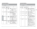
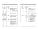
TIME CODE 400 VITC LINE-1 SEL (525) Selects the vertical interval line for adding VITC-1........................................... 61
400p VITC LINE-1 SEL (625) Selects the vertical interval line for adding VITC-1........................................... 61
401 VITC LINE-2 SEL (525) Selects the vertical interval line for adding VITC-2........................................... 61
401p VITC LINE-2 SEL (625) Selects the vertical interval line for adding VITC-2........................................... 61
402 CTL DF SELECT (525) Sets the CTL counter to operate in NONDROP/DROP frame mode ............... 61
403 REGEN MODE Selects what elements of time the code (TC, UB) are regenerated................. 61
409 EXT REGEN TC Selects external source (LTC/ VITC) for regeneration ..................................... 62
410 AUTO REGEN MODE Selects the edit mode in which time code is regenerated. ............................... 62
421 TCG CF FLAG Turns the color frame flag ON/OFF for the time code bit ................................. 62
450 SUB TC (VITC) REC Selects whether incoming VITC is recorded onto the Sub-Time Code ............ 62
451 VITC OUT SELECT Selects the VITC time code output source (Main/Sub) time code ................... 62
452 SEARCH LTC Selects whether LTC time code is output in the Search mode......................... 62
457 UB PRESET AUTO Selects if the user bit data stored in the memory is recorded preferentially..... 63
ON-SCREEN 501 CHARA H POSITION Sets the horizontal display position of the on-screen data............................... 63
502 CHARA V POSITION Sets on-screen data vertical display position ................................................... 63
504 INFORMATION SELECT Selects the type of information shown by the on-screen display...................... 63
505 REMAIN ENABLE Enables/ disables the tape “Remaining Time” display indication ..................... 63
512 MUTING/ALARM MESSAGE Selects whether “MUTING” or “CONDITION ALARM” appears on-screen...... 64
513 EDIT ON SCREEN ON/OFF of edit on-screen display................................................................... 64
TBC.FRAME 601 V.BLANK MASK Turns the V sync section masking ON/OFF during playback........................... 64
MEMORY 620 DUBBING LOOP Enables/ disables the Dubbing Loop (multi-gen test) function ......................... 64
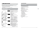
5 MENU SWITCH SETTING DETAILS
5-1 MENU SWITCH LIST
43
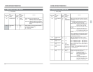
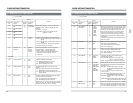
Selects the reference sync signal used by the
servo system.
EXT :Synchronizes with the signal applied to
the[REF] input connector regardless of
VCR mode (playback or record).
AUTO :Synchronizes with the signal applied to
the [REF] input connector during
playback.The VCR locks to the video
input during recording. (If no signal is
present on the [REF] connector and video
input connector, the VCR synchronizes to
an internal clock signal regardless of this
menu's setting).
Switches the operation mode lock ON/OFF.
Set to ON to lock the VCR in the current mode.
When “OPERATION LOCK” is ON, you cannot
operate the control buttons, switches, knobs and
dials on the VCR or change any menu switch
settings other than this menu switch itself. Only the
[POWER] switch and the [PHONES LEVEL] adjust
knob remain operable.
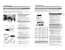
5 MENU SWITCH SETTING DETAILS
5-2 MENU SWITCH SETTING CONTENT
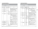
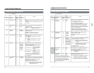
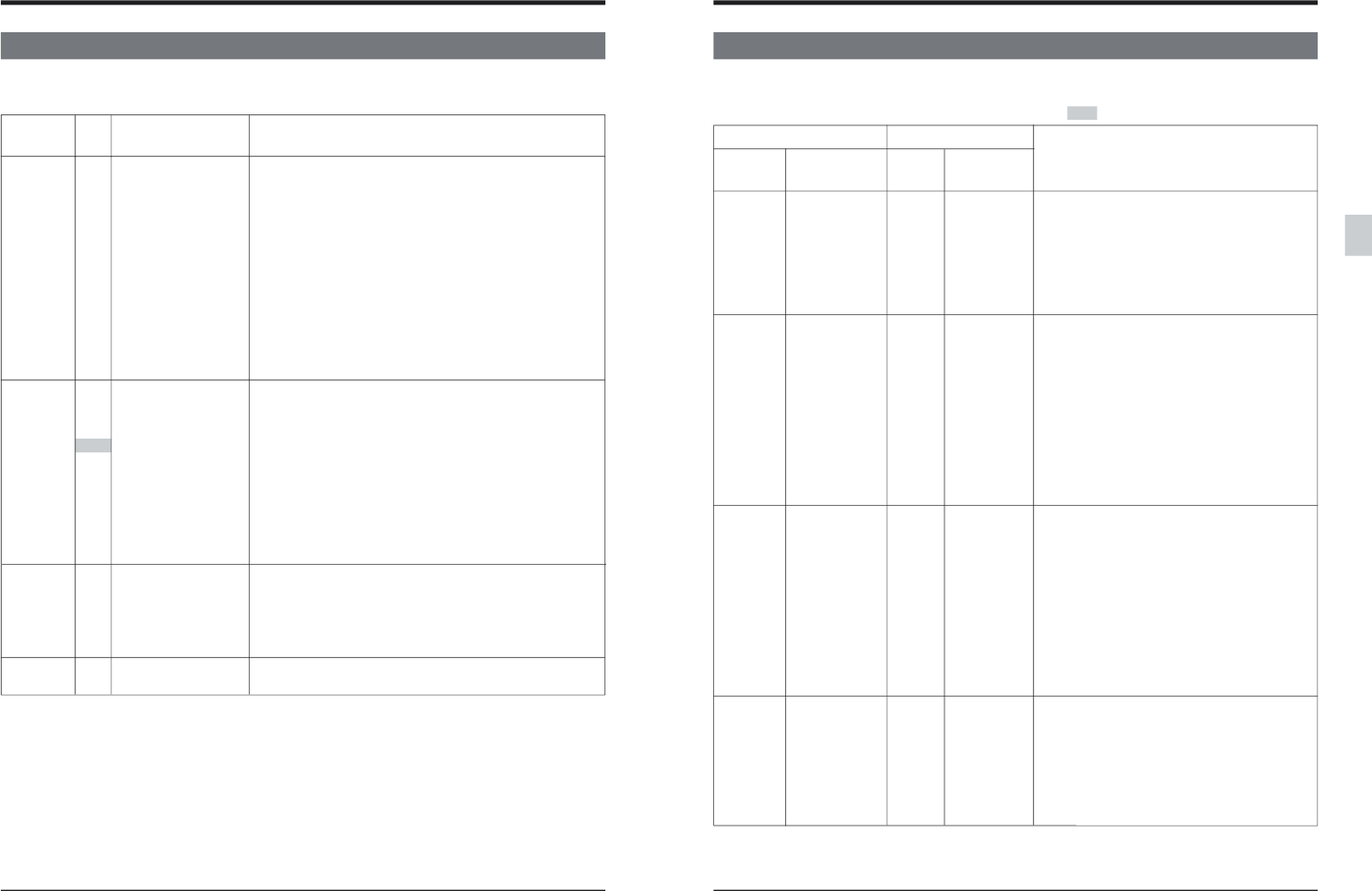
<SERVO> [ ] : Factory setting Functions enclosed in
are not available on the PAL SYSTEM.
Menu SW On-screen Counter
On-screen
No. display display display
002 OPERATION [0] [OFF]
LOCK 1 ON
003 SYNC SELECT 1 EXT
[3] [AUTO]
005
AUTO TRACKING
0 OFF
[1] [ON]
008 CAP LOCK (525) [0] [SW SEL]
12 FIELD
24 FIELD
Selects manual or automatic tracking adjustment in
the Play mode.
ON :The tracking value is automatically adjusted
to the optimum position when the Play mode
is engaged. The [TRACKING] knob is not
operable. When the Automatic Tracking mode
is engaged, tracking adjustment takes several
seconds. During this time, audio output
signals are derived from the linear tracks.
OFF: Tracking can be adjusted manually with the
[TRACKING] knob. When the meter
indication is set to “Tracking”, the
[TRACKING] button blinks.
Selects the color frame servo sync system for
NTSC signals.
SW SEL: The color frame servo setting is
determined by the sub panel’s [CF]
switch setting.
2 FIELD : The frame servo is set. Color framing is
not executed.
4 FIELD : 4 field color frame servo is executed.
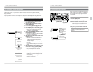
When the contents of a menu item differ for NTSC and PAL, this is indicated after the menu item name by (525)
for NTSC and (625) for PAL. With PAL, “p” is shown after the menu No.
Item
Content
Setting