


52
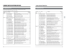
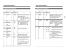
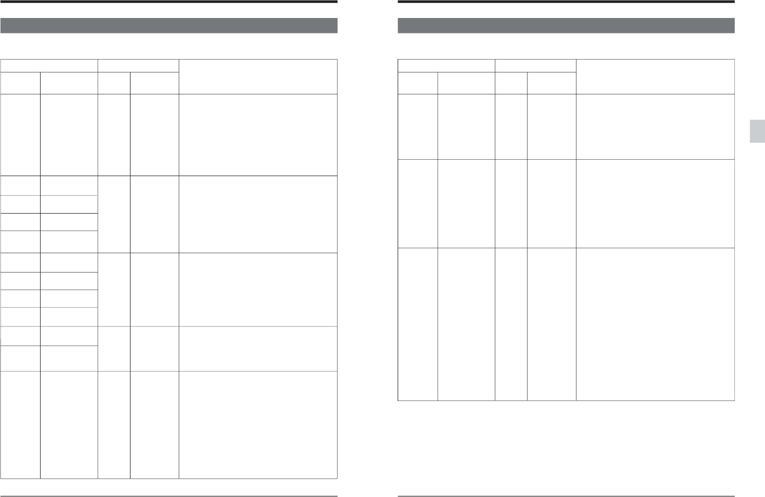
Menu SW On-screen Counter On-screen
No. display display display
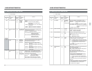
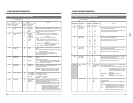
223
CH3/4 OUT SEL
[0] [MUTING]
AT 2CH 1 CH1/CH2
224
AUDIO IN LEVEL
0 –6DB
CH1 1 0DB
225
AUDIO IN LEVEL
[2] [4DB]
CH2 3 –20DB
226
AUDIO IN LEVEL
CH3
227
AUDIO IN LEVEL
CH4
228
AUDIO OUT LEVEL
0 –6DB
CH1 1 0DB
229
AUDIO OUT LEVEL
[2] [4DB]
CH2
230
AUDIO OUT LEVEL
CH3
231
AUDIO OUT LEVEL
CH4
232 AUDIO MON 0 –6DB
LEVEL LCH 1 0DB
233 AUDIO MON [2] [4DB]
LEVEL RCH
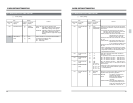
236 PRO 48K S.R. [0] [AUTO]
CONV. 1 ON
[ ] : Factory setting
Item
Content
Setting
Enables the sampling rate converter even when
the input signal is a professional 48K AES/EBU
signal.Always ON for digital audio signals
conforming to other specifications.
AUTO: The sampling rate converter is set to
OFF.
Use this position normally.
ON :The sampling rate converter is forced
ON.
Set to this menu position when the incoming
AES/EBU signal cannot be externally
synchronized (audio signal is not in sync with
video signal).
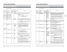
When audio recorded only on CH1 and CH2 with
the BR-D40, BR-D80, BR-D85 or BR-D750 is
played back, select whether or not to output this
audio on CH3 and CH4 as well.
MUTING : Audio is not output.
CH1/CH2 : Audio is output. Signals on CH1 are
output to CH3 and signals on CH2 are
output to CH4. The audio level meter
does not move.
Selects the analog audio reference input level.
Sets each of the four channels (CH1 to CH4).
–6DB : Sets the reference level to –6dB.
0DB : Sets the reference level to 0 dB.
4DB : Sets the reference level to 4 dB.
–20DB: Sets the reference level to –20dB.
Selects the analog audio reference output level.
Sets each of the four channels (CH1 to CH4).
-6DB : Sets the reference level to -6 dB.
0DB : Sets the reference level to 0 dB.
4DB : Sets the reference level to 4 dB.
Selects the reference level of the audio output from
the rear panel [AUDIO MONITOR] connector.
-6DB : Sets the reference level to -6dB.
0DB : Sets the reference level to 0 dB.
4DB : Sets the reference level to 4 dB.
5-2 MENU SWITCH SETTING CONTENT
5 MENU SWITCH SETTING DETAILS
53
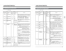
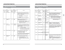
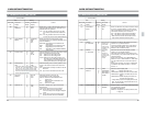
Disables the embedded audio signal from the SDI
output signal
Selects whether or not digital audio signals are
output from the rear panel [SERIAL V/A OUT]
connector together with the video signals.
OFF: Digital signals are not output.
ON : Digital signals are output.
Noise will be generated in embedded audio signals
if the embedded audio signals are input from a
different system than the reference sync signals, or
if no reference sync signals are input. This switch
allows you to specify whether or not to remove this
noise (effective only when the SA-D95 is installed).
NORMAL :Noise is not removed. Normally
set to this position.
NOISE REDUCE :Processes the audio signal to
reduce noise.
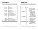
Menu SW On-screen Counter On-screen
No. display display display
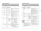
237
EMBEDDED
0 OFF
AUDIO
[1] [ON]
247 DIG AUD AT [0] [NORMAL]
ASYNC IN 1 NOISE
REDUCE
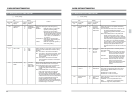
251 CH3/4 SOURCE [0] [CH3pSW/
SEL. CH4pSW]
1 CH3pCH1/
CH4pSW
2 CH3pSW/
CH4pCH2
3 CH3pCH1/
CH4pCH2
[ ] : Factory setting
Item
Content
Setting
CH3pSW/CH4pSW: CH3 and CH4 audio input
signals are determined by the front panel’s
audio signal select buttons.
CH3pCH1/CH4pSW: CH3 audio input signals
come from the same source as CH1 audio
input signals.
CH4 audio input signals are determined by the
front panel’s audio signal select buttons.
CH3pSW/CH4pCH2: CH3 audio input signals
are determined by the front panel’s audio
signal select buttons.
CH4 audio input signals come from the same
source as CH2 audio input signals.
CH3pCH1/CH4pCH2: CH3 audio input signals
come from the same source as CH1 audio
input signals.
The CH4 audio input signals come from the same
source as CH2 audio input signals.
5-2 MENU SWITCH SETTING CONTENT
5 MENU SWITCH SETTING DETAILS