


106
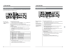
During playback
During EE output
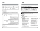
TCG CF FLAG setting CF FLAG being recorded on tape
OFF OFF information OFF information OFF information is recorded
is output is output
ON ON information ON information ON information
is output is output is recorded
OFF information
is recorded
AUTO The information The same ON information
recorded on the setting as the is recorded
tape is output. one of TCG CF
FLAG being
recorded on the
tape is output.
OFF information
is recorded
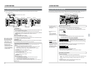
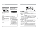
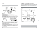
11-2 COLOR FRAME SERVO SETTING
11 EDITING
Ⅵ Color frame reference
VIDEO IN LINE IN monochrome input
LINE IN color signal input COMPONENT IN
REF IN
SDI IN
REC EDIT PB PB REC PB
REF IN is LINE IN LINE IN REF IN REF IN REF IN
Gen locking
REF IN is not Internal Color frame Internal reference
Gen locking reference information is signal
signal recorded according
to the time code.
The color frame sync condition of the playback shown in the table above changes depending on the setting of menu switch No. 008
<CAP
LOCK>.
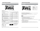
Ⅵ TC color frame flag setting
●The time code color frame flag can be set and recorded only when the front sub panel’s [TIME CODE]
switches are set as follows.
[INT/EXT] switch : INT
[PRESET/REGEN] switch : PRESET
When the [TIME CODE] switches are set as above, the time code color frame flag is recorded according to
the setting of menu switch No. 421 <TCG CF FLAG MODE>.
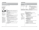
Menu switch
NO. 421 <TCG
CF FLAG
MODE>
* The set time code value may shift when menu switch No. 421 <TCG CF FLAG MODE> is set to “ON” or “AUTO” and recording is
performed with TC PRESET.
●When recording time code with the [INT/EXT] switch set to “INT”
and the [PRESET/REGEN] switch set to “PRESET” (except in
editing)
*Time code is based on the information recorded before the
recording is paused. (i.e. “REC” [ “PAUSE” [ “REC” ) with the
REGEN or REC RUN setting.
●To record time code during assemble or time code insert editing
(with tape recorded on BR-D95U).
*Set menu switch No. 410 <AUTO REGEN MODE> to a valid
setting (or set to “OFF” if the [PRESET/REGEN] switch is set to
“REGEN”) and the [INT/EXT] switch is set to “INT” under the 4-
field (8-field in PAL) color frame servo.
●When recording time code under any conditions except those
described above.
●When recording time code with the [INT/EXT] switch set to “INT”
and the [PRESET/REGEN] switch set to “PRESET” (except in
editing)
*Time code is based on the information recorded before the
recording is paused. (i.e. “REC” [ “PAUSE” [ “REC” )with the
REGEN or REC RUN setting.
●To record time code during assemble or time code insert editing
(with tape recorded on BR-D95U).
*Set menu switch No. 410 <AUTO REGEN MODE> to a valid
setting (or set to “OFF” if the [PRESET/REGEN] switch is set to
“REGEN”) and the [INT/EXT] switch is set to “INT” under the 4-
field (8-field in PAL) color frame servo.
●When recording time code under any conditions except those
described above.
Ⅵ 9P color frame flag
9P color frame flag is set when the setting of menu switch No. 387 <CF FLAG REPLY> matches that of menu
switch No. 008 <CAP. LOCK>.
107
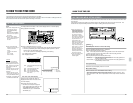
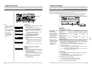
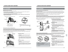
11-3 SWAP EDITING
11 EDITING
This unit is provided with a SWAP editing function which enables automatic editing without a controller. When this
unit is connected to a player provided with a RS-422 serial remote connector (9-pin), you can operate both units
using the recorder’s controls.
An on-screen function allows you to check editing data for faster, more efficient editing.
During swap editing, all the player can be operated from the recorder.
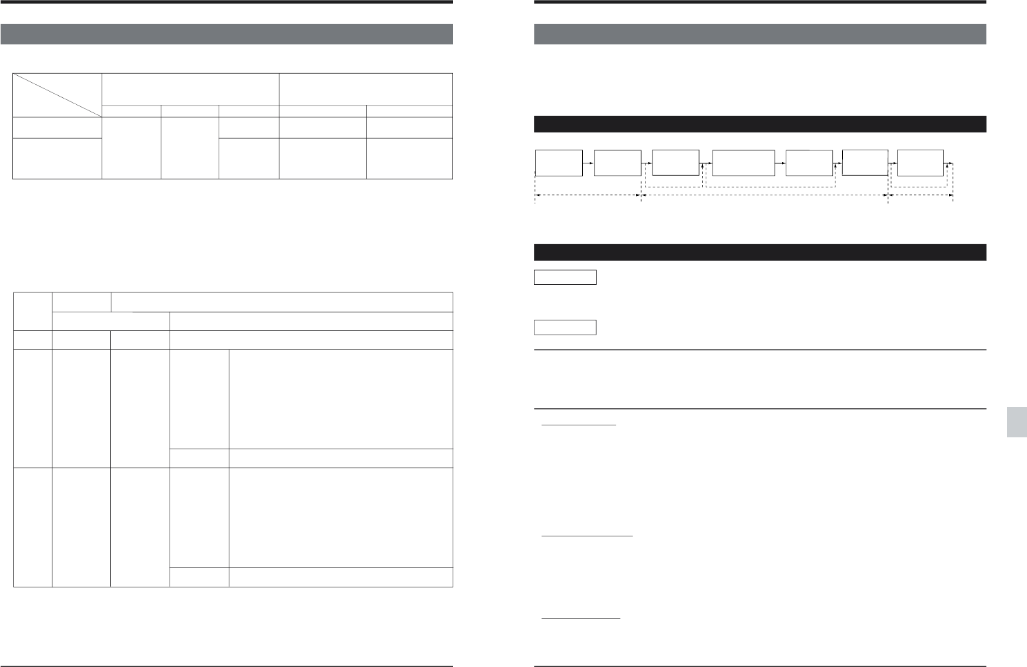
Editing procedure
STEP-1 STEP-2 STEP-3
STEP-4
STEP-5
STEP-6
STEP-7
Edit mode
selection
Preview editing
(rehearsal)
Editing
(actual)
Preparation Editing
Check
Next
edit
Review
(check)
Edit point
correction
Edit point
entry
Preparation
● When only edit start is performed automatically, steps 4, 5 and 7 can be omitted depending on the editing
method (for example, preview editing is not required).
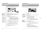
STEP-1 preparation
• No. 328 <EDIT POINT CLEAR>: Set whether or not
the edit IN point is canceled when editing is complete.
• No. 367 <EDIT INTERRUPTION>: Set whether or
not the editing operation is stopped when an error
occurs in the video signal during preroll editing .
• No. 372 <P+R AT SWAP MODE>: Set whether or
not pressing the [RECORDER] and [PLAYER]
buttons simultaneously is possible.
• No. 373 <MATCH FRAME>:This setting determines
whether or not the match frame function is used.
• No. 390 <SWAP VTR SELECT>: Set according
to the type of player VCR. Normally set to “AUTO”.
• No. 391 <SYNCHRONIZATION>: Switch the
Bump mode ON/OFF during swap editing.
• No. 393 <SYNC GRADE>: Select the editing
accuracy during swap editing.
• No. 395 <AUTO EE>: Set whether or not the auto
EE function is used during swap editing.
Set to “AUTO-EE (1)” when using only one
monitor for editing.
• No. 513 <EDIT ON SCREEN>: Selects whether
or not the edit display is shown on screen during
editing.
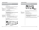
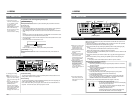
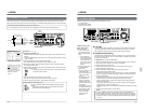
Connection
• Make sure all video and audio input/output connectors are properly connected.
• Connect the BR-D95U’s [REMOTE OUT(9P)] connector to the player’s RS-422 serial remote connector with
the 9-pin remote cable.
Setting
Ⅲ Setting the player
• Set the VCR operation mode to the REMOTE mode.
• Adjust the video control parameters.
• Adjust the playback level with the audio playback level adjust knobs (this is not necessary for UNITY).
• Set the edit OUT point registering method with menu switch No. 373.
Ⅲ Setting the recorder
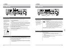
● Front panel setting
• Set the VCR operation mode to “Local” with the
[REMOTE] button (the [REMOTE] indicator on
the display goes out).
• Select the input signal with the video and audio
input signal select buttons.
• Adjust the recording level with the audio recording
level adjust knobs (this is not necessary for
UNITY).
• Set the counter mode with the [COUNTER]
button.
● Front sub panel setting
Set the time code-related switches for time code
editing.
(When editing the time code, be sure to input an
external sync signal to the recorder and player.)
• [INT/EXT] switch: Set to “INT”.
• [REC/FREE] switch: Set to “FREE”.
• [PRESET/REGEN]: Set to “PRESET”.
● Menu switch setting
• No. 003 <SYNC SELECT>: Set to “EXT (1)” to
synchronize with an external sync signal.
• No. 320 <PREROLL TIME>: Set the preroll time.