


68
7 RECORDING
7-1 PREPARATION FOR RECORDING
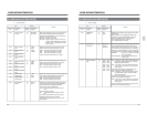
POWER
ON
I
OFF
O
M
H
F
S
REC
MENU
PLAY
PAUSE/ STILL
REW
STOP
FF
EJECT
PHONES
CH1
CH2
CH3
CH4
REC
PLAY
PULL FOR VARIABLE
TRACKING
CH1
CH1
CH2
CH3
CH4/
TRACKING
SET
HOLD
PB
PB/EE
COUNTER
UB
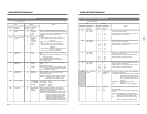
CONDITION
AUDIO
INPUT
VIDEO
INPUT
AUDIO
MONITOR
PULL
RELEASE
RESET
VCON
REMOTE
TOP VIDEO AUDIO
OTHERSON SCREENTIME CODESERVO/SYS
USER
INSERT
STAND BY
PLAYER
SEARCH
VAR
P.PLAY
DA3
DA2
DA1VIDEO
ASSEM
IN
ENTRY
OUT
CANCEL
SHIFT
REVIEW
METER MODE
TRACKING
FINE
PREVIEW
AUTO EDIT
PREROLL
TC
RECORDER
DA4
VIDEO CASSETTE RECORDER
BR-D95U
STILL
X-1
REV
FWD
X1
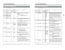
CH2
CH3
CH4
CH1
CH2
CH3
CH4
CH1
CH2
CH3
CH4
SIF
SDI
AES/EBU
AUDIO INPUT / AUDIO MONITOR SELECT
LINE
CPN
L
ANALOG
R
PULL
RELEASE
CTL
P.READ
AUTO
OFF
V.VAR
REMOTE
PB/EE
16:9
TC
UB
DF
SERVO
GENCF
AP
525
OVER
–60
–2
–4
+2
+4
0
–40
–30
–20
–10
0
dB
dB
R
P
OVER
–60
–2
–4
+2
+4
0
–40
–30
–20
–10
0
dB
dB
R
P
OVER
–60
–2
–4
+2
+4
0
–40
–30
–20
–10
0
dB
dB
R P
OVER
–60
–2
–4
+2
+4
0
–40
–30
–20
–10
0
dB
dB
R
P
625
CONDITION
CTL
REMOTE
16:9
TC
UB
GEN
525
625
Variable Motion
COMPONENT DIGITAL
Counter mode
indicators
When recording wide aspect
screen ID (menu switch No. 103)
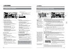
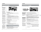
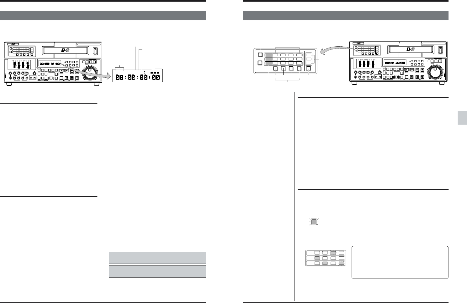
Front panel switch setting
1. Select the input video signal.
2. Select the input audio signal.
3. Select the audio monitor output.
Select the audio monitor output from the rear
panel [AUDIO MONITOR OUT] connectors or the
front panel [PHONES] jack.
For details of steps 1 to 3, refer to page 70.
4. Set the tape counter mode.
Set the time data to be shown on the counter
display and on-screen display. “CTL”, “TC” or
“UB” will be shown on the counter display.
5. Engage the Remote mode.
To operate this unit locally, press the [REMOTE]
button so that the “REMOTE” indicator on the
counter display goes out.
Menu switch setting
Set the menu switches as required.
● Video items
Reference sync signal items
•Select the reference sync system.
No. 003 <SYNC SELECT> ..... Page 43
Set to “EXT” to synchronize with an external sync
signal.
● Video items
•Wide aspect ID signal selection
No. 103 <WIDE ASPECT ID REC> ... Page 44
•Component video input level selection (NTSConly)
No. 104 <COMPONENT LEVEL> ... Page 44
•Recording a signal from the built-in signal
generator
No. 111 <VD REC SIGNAL SEL.> ... Page 44
Select a color bar signal, black picture, multi burst
or pulse & bar.
For time code and editing settings, refer to “10.
HOW TO USE THE TIME CODE” and “11. EDITING”.
* This unit cannot be used for sound-on-sound
editing. Inserted audio signals are delayed.
● Audio items
• Audio recording level adjustment mode selection
No. 215 <AUD REC VOLUME MODE 1>
For details, refer to page 50.
• Search audio recording selection
No. 219 <SEARCH REC CH> ..... Page 51
Select the type of audio to be recorded on the cue
track (2 tracks).
• Audio monitor output mode selection
No. 222 <MONITOR MIX MODE> ..... Page 51
Select the way mixed audio is output from the
[AUDIO MONITOR OUT] connectors or
[PHONES] jack.
• Input audio level selection (by channel from 1 to 4)
No. 224 to No. 227 <AUDIO INPUT LEVEL
CH 1–4> ... Page 52
Select the audio input level of the rear panel
[AUDIO IN] connectors from “+4 dB”, “0 dB”,
“-6 dB” and “-20 dB” for each channel.
● Record pause selection
• Backspacing selection
No. 302 <BACKSPACE> .... Page 54
● Set the relationship between the serial digital
video signal input and AES/EBU input
(Only when the optional SA-D95U digital inter-
face board is installed)
• To input asynchronous professional 48 kHz AES/
EBU signal
No. 236 <PRO 48K S.R.CONV.> ... Page 52
Set to “AUTO” to input a serial digital audio signal
with professional 48 kHz sampling frequency from
a source unit which cannot be genlocked.
REMOTE indicator (when using the
remote control unit)
When this unit is synchro-
nized externally
69
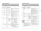
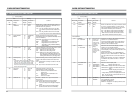
CH1
AUDIO
INPUT
VIDEO
INPUT
AUDIO
MONITOR
CH2
CH3
CH4
CH1
CH2
CH3
CH4
CH1
CH2
CH3
CH4
SIF
SDI
AES/EBU
AUDIO INPUT / AUDIO MONITOR SELECT
LINE
CPN
L
ANALOG
R
CH1
CH2 CH3
CH4
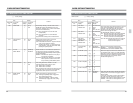
POWER
ON
I
OFF
O
M
H
F
S
REC
MENU
PLAY
PAUSE/ STILL
REW
STOP
FF
EJECT
PHONES
CH1
CH2
CH3
CH4
REC
PLAY
PULL FOR VARIABLE
TRACKING
CH1
CH1
CH2
CH3
CH4/
TRACKING
SET
HOLD
PB
PB/EE
COUNTER
UB
CONDITION
AUDIO
INPUT
VIDEO
INPUT
AUDIO
MONITOR
PULL
RELEASE
RESET
VCON
REMOTE
TOP VIDEO AUDIO
OTHERSON SCREENTIME CODESERVO/SYS
USER
INSERT
STAND BY
PLAYER
SEARCH
VAR
P.PLAY
DA3
DA2
DA1VIDEO
ASSEM
IN
ENTRY
OUT
CANCEL
SHIFT
REVIEW
METER MODE
TRACKING
FINE
PREVIEW
AUTO EDIT
PREROLL
TC
RECORDER
DA4
VIDEO CASSETTE RECORDER
BR-D95U
STILL
X-1
REV
FWD
X1
CH2
CH3
CH4
CH1
CH2
CH3
CH4
CH1
CH2
CH3
CH4
SIF
SDI
AES/EBU
AUDIO INPUT / AUDIO MONITOR SELECT
LINE
CPN
L
ANALOG
R
PULL
RELEASE
CTL
P.READ
AUTO
OFF
V.VAR
REMOTE
PB/EE
16:9
TC
UB
DF
SERVO
GENCF
AP
525
OVER
–60
–2
–4
+2
+4
0
–40
–30
–20
–10
0
dB
dB
R P
OVER
–60
–2
–4
+2
+4
0
–40
–30
–20
–10
0
dB
dB
R P
OVER
–60
–2
–4
+2
+4
0
–40
–30
–20
–10
0
dB
dB
R P
OVER
–60
–2
–4
+2
+4
0
–40
–30
–20
–10
0
dB
dB
R
P
625
Variable Motion
COMPONENT DIGITAL
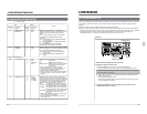
7 RECORDING
7-2 INPUT VIDEO AND AUDIO SIGNAL SELECTION
The video and audio input signal select method is different depending on the setting of menu switch No. 371 <INPUT
SELECT SAFETY>. The procedure when menu switch No. 371 <INPUT SELECT SAFETY> is set to “OFF” is
described below.
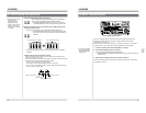
● When the [AUDIO MONITOR]
button is illuminated, the audio
channel indicator can be used
to select the audio monitor
signal. The orange “L” and “R”
indicators show the audio
monitor output connectors.
● The input source for CH3 and
CH4 audio signals can be
selected with menu switch No.
251 <CH3/4 SOURCE SEL.>.
● When the SDI, AES/EBU, and
ANALOG indicators are lit,
audio signals from the built-in
signal generator are recorded.
Select audio signals from the
built-in signal generator with
menu switches No. 253 to 256
<CH1 to 4 REC SIGNAL
SEL.>.
Ⅲ Input video signal selection
Select the signal from rear panel video input connector or built-in signal generator.
1. Press the [VIDEO INPUT] button to select the video signal.
The [VIDEO INPUT] indicator corresponding to the pressed button lights.
SIF :Input a serial digital video signal to the rear panel [SERIAL V/A IN]
connector (effective only when the optional SA-D95U digital interface
board is installed).
LINE:Input composite video signals to the rear panel [COMPOSITE LINE IN]
connector.
CPN :Input component video signals to the rear panel [COMPONENT IN] connector.
SIF, LINE, CPN lit simultaneously: Records a color bar, black picture, multi
burst or pulse & bar from the built-in signal generator (select with menu
switch No. 111 <VD REC SIGNAL SEL.>).
Blinking :The indicator blinks if no signal is input or if the wrong type of signal is
input.
ⅢWhen composite monochrome signals are input, use the COMPONENT Y input, not the
LINE input. This will minimize degradation during signal processing. In this case, set
menu switch No. 104 <CPN LEV./SETUP> to “HIGH/ON” or “HIGH/OFF” in the [525]
mode.
● Changing the video and
audio input signal select
method
Set menu switch No. 371
<INPUT SELECT SAFETY> to
“ON (1)” to prevent the setting
from being changed acciden-
tally.
When set to “ON (1)”, the input
signal select methods are as
follows.
• Video signal: Press the
[VIDEO INPUT] button while
pressing the [SHIFT] button.
• Audio signal: Press the audio
signal select button while
pressing the [SHIFT] button.
VIDEO INPUT
indicator
[VIDEO INPUT] button
Audio input
connector names
[AUDIO INPUT] button
Audio channel indicators
Audio signal select buttons
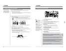
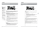
Ⅲ Input audio signal selection
This unit is provided with independent four-channel input connectors for
analog audio, serial digital audio (AES/EBU), and SDI audio.
Select the audio signal to be recorded on each of the four audio channels (1to 4).
1. Press the [AUDIO INPUT] button so that the [AUDIO INPUT] button is
illuminated.
● When the [AUDIO INPUT] button is illuminated, the audio channel indicator
can be used to select input audio signal.
2. Select the audio signal to be recorded on each of four audio channels
(1 to 4) by pressing the audio signal select button.
The channel indicator of the selected audio signal lights.
AUDIO
INPUT
CH1
CH2
CH3
CH4
CH1
CH2
CH3
CH4
CH1
CH2
CH3
CH4
SDI
AES/EBU
AUDIO INPUT / AUDIO MONITOR SELECT
L
ANALOG
R
Notes:
• Audio can only be input to the [AES/EBU] or [SERIAL V/
A] connectors when the optional SA-D95U digital interface
board is installed.
• Always input external sync signals when inputting digital
signals. Both video and audio must be synchronized with
the external sync signal.
(Illustrated example)
• The first audio channel on the tape: Audio to the [AES/EBU CH1] connectors is recorded.
• The second audio channel on the tape: Audio to the [AUDIO IN CH2] connectors is recorded.
• The third audio channel on the tape: Audio to the [SERIAL V/A IN] connectors is recorded.
• The fourth audio channel on the tape: Audio to the [AUDIO IN CH4] connectors is recorded.
● The channel indicator blinks if
the selected signal does not
conform to the standard.