


122
12-3 DUBBING LOOP FUNCTION
12 EDITING SYSTEM PHASE ADJUSTMENT
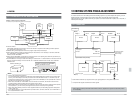
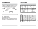
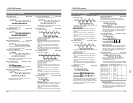
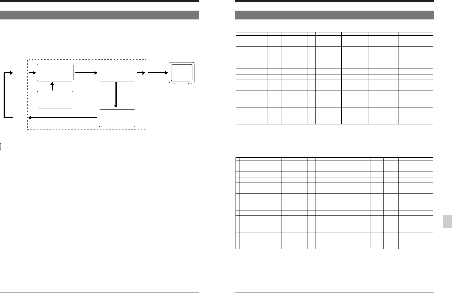
The dubbing loop function allows you to effectively perform analog video signal adjustment.
The dubbing loop function loops video signals and generates color bar signals from the built-in signal generator.
The picture passes through the looped video signal circuit and is fed back and stored in the memory circuit. Then,
instead of outputting color bar signals from the signal generator, the picture stored in memory is output and
passed through the looped video signal circuit the designated number of times. The same effect is obtained each
time this pseudo-dubbing is repeated and the video signal can be adjusted according to the picture output.
VIDEO
LINE
IN
Video signal
recording circuit
Color bar signal
Built-in signal
generator
VIDEO
LINE1
OUT
Color bar output
Video signal
playback circuit
Color bar
Stored in the
memory circuit
VIDEO
LINE2
OUT
Color bar
output
Monitor TV
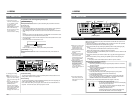
1. Connect the rear panel's video input connector and video output connector with the cable.
2. Set menu switch No. 620 <DUBBING LOOP> to activate the dubbing loop function.
OFF (0) : The dubbing loop function is disabled.
3 TIMES (1) : The dubbing loop function repeats 3 times.
5 TIMES (2) : The dubbing loop function repeats 5 times.
10 TIMES (3): The dubbing loop function repeats 10 times.
• When the menu switch is set to any position except OFF (0), the Dubbing Loop mode is activated.
3. While referring to the color bar on the monitor, adjust the video control parameters so that color changes in the
picture are minimized.
4. To end the dubbing loop mode, set menu switch No. 620 <DUBBING LOOP> to “OFF (0)” and press the [SET]
button.Normal operation is restored.
Note
• For the dubbing loop function, use the composite video signal.
123
0
Complate
Error
Cassette
Out
Not Target
ACK
NAK
12 3
Play
Stop
4
Enter
ClearError
In Shift(+)
In Shift(-)
Out Shift(+)
Out Shift(-)
Still
5
In Entry
Out Entry
In Flag
Reset
Out Flag
Reset
In Flag
Recall
Out Flag
Recall
Clear
Go to In
Goto Out
Memory
Memory
Search
67
Rom
Version
89A
Standby
On
Standby
Off
Preroll
Eject
Valiable
Fwd
Valiable
Rev
Ff
Rew
C
Full Ee
On
Ee off
Rec
Rec Pause
D
Device Type
Request
Memory
Switch Sense
Tape Remain
Sense
Status
Sense
TC Data
Sense
CTL Data
Sense
Panel Switch
Sense
JVC Status
Sense
E
CTL Data
Reset
In Data
Preset
Out Data
Preset
Timer Mode
Select
Analog Data
Select
Panel Switch
Set
Memory
Switch Preset
F
JVC-1 Table
Select
Basic Table
Select
Rec Request
VTR Ind.
0
1
2
3
4
5
6
7
8
9
A
B
C
D
E
F
B
Play after
CueUp with Data
Fwd
Shuttle
Rev
Shuttle
0
Complate
Error
Cassette
Out
Not Target
ACK
NAK
12 3
Play
FwdShuttle
X4
FwdShuttle
X0.09
FwdShuttle
Still
FwdShuttle
X6
Stop
4
Enter
ClearError
CueUp with
Data
In Shift(+)
In Shift(-)
Out Shift(+)
Out Shift(-)
RevShuttle
X1
RevShuttle
X4
RevShuttle
X0.09
RevShuttle
Still
RevShuttle
X6
Still
5
In Entry
Out Entry
In Flag
Reset
Out Flag
Reset
In Flag
Recall
Out Flag
Recall
Clear
Go to In
Goto Out
Memory
Memory
Search
6789 A
Standby
On
Standby
Off
Preroll
Eject
Valiable
Fwd
Valiable
Rev
Ff
Rew
C
Auto Edit
Preview
Review
Full Ee
On
Ee off
Select Ee
On
Ee off
Rec
Rec Pause
Edit On
Edit Off
D
Preroll
Time Sense
Status
Sense
TC Data
Sense
CTL Data
Sense
In Data
Sense
Out Data
Sense
UB Data
Sense
JVC Status
Sense
SubTC Data
Sense
SubUB Data
Sense
E
TC Preset
UB Preset
CTL Data
Reset
In Data
Preset
Out Data
Preset
Edit Preset
Preroll Time
Preset
Timer Mode
Select
Edit Preset
(4ch)
TimeCode
Switch Preset
Memory
Switch Preset
F
JVC-1 Table
Select
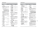
Basic Table
Select
Rec Request
VTR Ind.
0
1
2
3
4
5
6
7
8
9
A
B
C
D
E
F
B
CueUp with
Data
Fwd
Shuttle
Rev
Shuttle
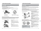
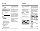
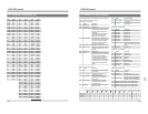
JVC-1 TABLE
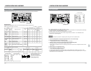
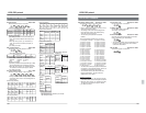
13 RS-232C protocol
13-1 Command tables
BASIC TABLE