


8
1 INTRODUCTION
1-1 OUTLINE
This manual consists of the following sections.
Section 1 INTRODUCTION
Read this section carefully as it describes the
precautions to be taken when operating this unit
and the type of cassette to be used.
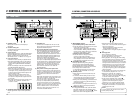
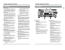
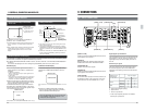
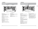
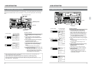
Section 2 CONTROLS, CONNECTORS AND
DISPLAYS
If you are already familiar with the operation of
professional VCRs, you will probably only need to
read this section to get started.
Section 3 CONNECTIONS
This section describes basic connections between
the BR-D95U and other units.
Section 4 MENU SWITCH SETTING
This unit incorporates a “Menu” function which
allows you to set a variety of switches on screen.
Setting procedures and setting items are described
in this section.
Section 5 MENU SWITCH SETTING DETAILS
This section describes the menu switch items and
setting contents in detail.
Section 6 PREPARATION
This section describes how to set up the unit prior
to operation and notes any precautions that need to
be taken.
Section 7 RECORDING
This section describes recording operations and
settings.
Section 8 PLAYBACK
This section describes playback operations and
settings.
Section 9 OTHER FUNCTIONS
This section describes the following special functions.
• Setting the unit to record or play back information
added to a video signal on an extra video line.
• Simultaneous operation of more than one VCR
• Cue-up function
Section 10 HOW TO USE TIME CODE
This section describes time code presetting,
recording, and time code playback operation.
Section 11 EDITING
This section describes the editing operation and
pre-read editing.
Section 12 EDITING SYSTEM PHASE ADJUST
MENT
This section describes internal TBC phase
adjustment and the dubbing loop function.
Section 13 RS-232C protocol
This section describes the data protocols used to
control of this unit with a personal computer or
other external RS-232C controller.
Section 14 TROUBLESHOOTING
This section suggests ways to handle potential
difficulties or malfunctions.
Section 15 APPENDIX
This section includes descriptions of optional units
and the index for this manual.
Section 16 SPECIFICATIONS
9
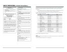
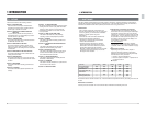
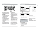
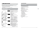
Use time Every 750H 1500H 3000H 4500H 6000H
Drum assembling ⅷⅷⅷⅷⅷ
(including heads)
Head cleaner ⅷⅷⅷⅷⅷ
Tape guide roller, etc. ⅜ⅷⅷⅷⅷ
Fixed head ଁ⅜ⅷ⅜ⅷ
Belt pinch roller, etc. ⅜ⅷⅷⅷⅷ
Driving system parts ⅜⅜⅜⅜ⅷ
The video cassette recorder/player incorporates precision components. Regular maintenance is necessary to
maintain the performance level required for professional use. The information below will help you determine a
maintenance schedule that will ensure optimum performance over a long period of time.
● Maintenance
Just as regular oil changes, brake checks, and
tune-ups are essential to keep your car running well
over a long period, your VCR must be maintained
regularly to ensure optimum long-term
performance.
Continued use of the VCR without maintenance
may lead to the following malfunctions.
●
Recording or playback cannot be executed.
●
Picture and sound distortion.
●
Repeated warnings (stopping the operation).
These malfunctions are mostly due to wear or
deterioration of the VCR's internal components.
Having these repaired can be expensive.
Moreover, a sudden malfunction can not only lead
to downtime and lost productivity, but can also
damage the video cassette.
1-2 MAINTENANCE
This table should be used as reference only. Actual maintenance requirements will vary according to how the unit
is used.
Maintenance consultation
Consult your local JVC dealer for more information about maintenance scheduling and costs.
1 INTRODUCTION
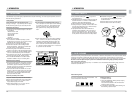
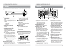
● Keeping track of operation (running) time
The total operation time reached by an ordinary
home VCR in five to six years may be reached by a
professional VCR in as few as five to six months.
Therefore, it is important to closely monitor the total
operation time. You can check the running time on
the provided hour meter (drum running time). The
hour meter is shown on the counter display or on-
screen display on the monitor.
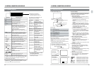
Hour meter indication
The hour meter can be displayed by selecting
“DRUM HOUR” on the menu switch setting screen.
For details, refer to “Hour meter indication” on page
39.
● Maintenance schedule
Depending on the operation time, inspect or
replace the following mechanism components.
Replace the drum assembly (including the heads)
and head cleaner every 750 hours.
ଁ: Cleaning, check and adjustment
⅜: Check or replace as required. If replacement is
not required, clean it.
ⅷ: Replace.