S3F80JB MICROCONTROLLER xv
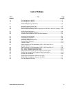
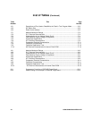
List of Tables
Table Title Page
Number Number
1-1 Pin Descriptions of 32-SOP......................................................................................1-7
1-2 Pin Descriptions of 44-QFP......................................................................................1-8
2-1 S3F80JB Register Type Summary...........................................................................2-5
4-1 Mapped Registers (Bank0, Set1) .............................................................................4-2
4-2 Mapped Registers (Bank1, Set1) .............................................................................4-3
4-3 Each Function Description and Pin Assignment of P3CON in 42/44 Pin Package ...4-32
5-1 S3F80JB Interrupt Vectors.......................................................................................5-6
5-2 Interrupt Control Register Overview .........................................................................5-7
5-3 Vectored Interrupt Source Control and Data Registers.............................................5-9
6-1 Instruction Group Summary......................................................................................6-2
6-2 Flag Notation Conventions.......................................................................................6-8
6-3 Instruction Set Symbols............................................................................................6-8
6-4 Instruction Notation Conventions..............................................................................6-9
6-5 Opcode Quick Reference.........................................................................................6-10
6-6 Condition Codes.......................................................................................................6-12
8-1 Reset Condition in STOP Mode When IPOR / LVD Control Bit is “1”
(always LVD-On)......................................................................................................8-8
8-2 Reset Condition in STOP Mode When IPOR / LVD Control Bit is “0” .......................8-8
8-3 Set 1, Bank 0 Register Values After Reset...............................................................8-15
8-4 Set 1, Bank 1 Register Values After Reset...............................................................8-17
8-5 Reset Generation According to the Condition of Smart Option.................................8-18
8-6 Guideline for Unused Pins to Reduced Power Consumption....................................8-19
8-7 Summary of Each Mode...........................................................................................8-20
9-1 S3F80JB Port Configuration Overview (44-QFP) .....................................................9-2
9-3 S3F80JB Port Configuration Overview (32-SOP).....................................................9-3
9-4 Port Data Register Summary....................................................................................9-4


