


CLOCK CIRCUITS S3F80JB
7-2
CLOCK STATUS DURING POWER-DOWN MODES
The two power-down modes, Stop mode and Idle mode, affect the system clock as follows:
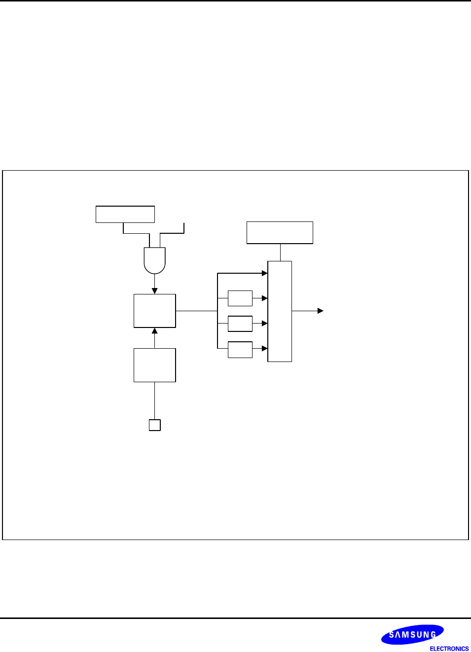
— In Stop mode, the main oscillator is halted. When stop mode is released, the oscillator starts by a reset
operation or by an external interrupt. To enter the stop mode, STOPCON (STOP Control Register) has to be
loaded with value, #0A5H before STOP instruction execution. After recovering from the stop mode by a reset
or an external interrupt, STOPCON register is automatically cleared.
— In Idle mode, the internal clock signal is gated away from the CPU, but continues to be supplied to the
interrupt structure, timer 0, timer 1, counter A and so on. Idle mode is released by a reset or by an interrupt
(external or internally generated).
NOTES:
1. An external interrupt with an RC-delay noise filter (for the S3F80JB INT0-9) is
fixed to release stop mode and "wake up" the main oscillator.
2. Because the S3F80JB has no subsystem clock, the 3-bit CLKCON signature
code (CLKCON.2-CLKCON.0) is no meaning.
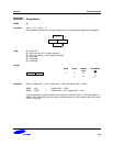
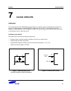
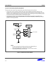
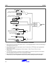
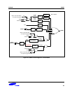
STOP
Instruction
Noise
Filter
INT Pin
(1)
Oscillator
Stop
Oscillator
Wake-up
1/16
M
U
X
CLKCON.3, .4
CPU CLOCK
1/2
1/8
STOPCON
Main
OSC
Figure 7-3. System Clock Circuit Diagram