


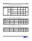
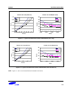
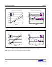
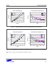

ELECTRICAL DATA (4MHz) S3F80JB
17-4
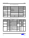
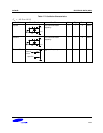
Table 17-2. D.C. Electrical Characteristics (Continued)
(T
A
= – 25 °C to + 85 °C, V
DD
= 1.7 V to 3.6 V)
Parameter Symbol Conditions Min Typ Max Unit
Supply Current
(note)
I
DD1
Operating Mode
V
DD
= 3.6 V
4 MHz crystal
–
5
9
mA
I
DD2
Idle Mode
V
DD
=3.6 V
4 MHz crystal
–
1.0
2.5
Stop Mode
LVD OFF, V
DD
= 3.6 V
–
1 6
I
DD3
Stop Mode
LVD ON, V
DD
= 3.6 V
–
10 20
uA
NOTE: Supply current does not include current drawn through internal pull-up resistors or external output current loads.
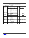
Table 17-3. Characteristics of Low Voltage Detect Circuit
(T
A
= – 25 °C to + 85 °C)
Parameter Symbol Conditions Min Typ Max Unit
Hysteresys voltage of LVD
(Slew Rate of LVD)
∆V
– – 100 300 mV
Low level detect voltage for
back-up mode
LVD – 1.7 1.9 2.1 V
Low level detect voltage for
flag indicator
LVD_FLAG – 1.95 2.15 2.35 V
NOTE: The voltage gap between LVD and LVD FLAG is 250mV.
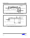
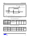
Table 17-4. Data Retention Supply Voltage in Stop Mode
(T
A
= – 25 °C to + 85 °C)
Parameter Symbol Conditions Min Typ Max Unit
Data retention supply
voltage
V
DDDR
–
1.5 – 3.6 V
Data retention supply
current
I
DDDR
V
DDDR
= 1.5 V
Stop Mode
– – 1
µA