


BASIC TIMER and TIMER 0 S3F80JB
10-4
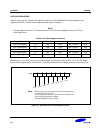
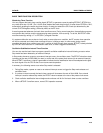
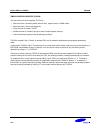
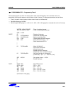
TIMER 0 CONTROL REGISTER (T0CON)
You use the timer 0 control register, T0CON, to
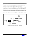
— Select the timer 0 operating mode (interval timer, capture mode, or PWM mode)
— Select the timer 0 input clock frequency
— Clear the timer 0 counter, T0CNT
— Enable the timer 0 overflow interrupt or timer 0 match/capture interrupt
— Clear timer0 match/capture interrupt pending conditions
T0CON is located in Set 1, Bank0, at address D2H, and is read/write addressable using register addressing
mode.
A reset clears T0CON to '00H'. This sets timer 0 to normal interval timer mode, selects an input clock frequency of
fOSC/4096, and disables all timer 0 interrupts. You can clear the timer 0 counter at any time during normal
operation by writing a "1" to T0CON.3.
The timer 0 overflow interrupt (T0OVF) is interrupt level IRQ0 and has the vector address FAH. When a timer0
overflow interrupt occurs and is serviced by the CPU, the pending condition is cleared automatically by hardware.
To enable the timer 0 mach/capture interrupt (IRQ0, vector FCH), you must write T0CON.1 to "1". To detect a
match/capture interrupt pending condition, the application program polls T0CON.0. When a “1” is detected, a
timer0 match or capture interrupt is pending. When the interrupt request has been serviced, the pending condition
must be cleared by software by writing a “0” to the timer0 interrupt pending bit, T0CON.0.